Table of Contents
Advertisement
Quick Links
Advertisement
Table of Contents

Related Manuals for Sakura SFP-KM-DLY Series


Summary of Contents for Sakura SFP-KM-DLY Series
- Page 1 Sakura Air Conditioner Sakura Air Conditioner User-friendly, Earth-friendly User-friendly, Earth-friendly SINGLE FAN (4-way discharge) TWIN FAN (6-way discharge) Hydronic Cassette SFP - KM - DLY Series ( Technical / Installation Manual ) Ref, S- 091 / 03 / 10 (A)
-
Page 2: Table Of Contents
WALL PAD INSTALLATIONS CONTROL SPECIFICATIONS SENSOR RESISTANCE R-T CONVERSION TABLE CONTROL AND POWER SUPPLY WIRING DIAGRAMS VALVE & VALVE CONNECTIONS (OPTIONAL) MASTER – SLAVE NET WORK BMS – HOST COMPUTER NET WORK (OPTIONAL) TROUBLE SHOOTING SAKURA - Total Air Conditioning Solution... -
Page 3: Cassette Model Assignments
PUMP FREE SERIES (for KM4) (for KM1,KM2) 2 PIPE SYSTEM 4 PIPE SYSTEM 6 WAY DISCHARGE (twin fan) 4 WAY DISCHARGE (single fan) 2 WAY DISCHARGE 1 WAY DISCHARGE CASSETTE TYPE NOMINAL AIR FLOW *10M FAN COIL UNIT SAKURA - Total Air Conditioning Solution... -
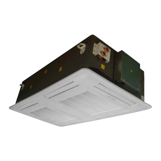
Page 4: Brief Introduction Of The Unit
Condensate drainage pipe delivery of treated air to adjacent room Lamp board (Receiver) Unit body Air return grille Mounting brackets Drainage hose Coil connection supporter Coil connection with air vent and partial drainage vent SAKURA - Total Air Conditioning Solution... -
Page 5: Unit Description
[Internal installation]: The 2 way on/off valve pre- PUMP MAINTENANCE BOARD is opened at the side installed at factory is available as optional. of unit body for easily service of the drainage pump in the case of necessary.(Fig.6) SAKURA - Total Air Conditioning Solution... - Page 6 (mm) Inch rows circuits Diameter Inner Outer FP-68/80KM4-P 1145 1349 14.1 3/8’’ FP-85/102/136KM4-P 1535 1739 14.1 3/8” FP-170/204/238KM4-P 1922 2126 14.1 3/8” FP-289KM4-P 2348 2552 14.1 3/8” FP-85/102/136/170KM6-P 2243 2447 14.1 3/8” Table 2 SAKURA - Total Air Conditioning Solution...
-
Page 7: Specifications - 2 Pipe System
Inlet water temp. 50ºC; Same water flow rate as for the cooling; The customized power of electric heater is available. The electric heater can be set as auxiliary heater booster or as primary heater, see control specifications. SAKURA - Total Air Conditioning Solution... - Page 8 Inlet water temp. 50ºC; Same water flow rate as for the cooling; The customized power of electric heater is available. The electric heater can be set as auxiliary heater booster or as primary heater, see control specifications. SAKURA - Total Air Conditioning Solution...
- Page 9 Inlet water temp. 50ºC; Same water flow rate as for the cooling; The customized power of electric heater is available. The electric heater can be set as auxiliary heater booster or as primary heater, see control specifications. SAKURA - Total Air Conditioning Solution...
- Page 10 Inlet water temp. 50ºC; Same water flow rate as for the cooling; The customized power of electric heater is available. The electric heater can be set as auxiliary heater booster or as primary heater, see control specifications. SAKURA - Total Air Conditioning Solution...
-
Page 11: Specifications - 4 Pipe System
19.05(3/4") mm(in) Cooling: Entering air temperature: Dry bulb 27ºC, Wet bulb 19ºC; Inlet water temp. 7ºC; Outlet water temp. 12ºC; Heating: Entering air temperature: 20ºC; Inlet water temp. 70ºC; Outlet water temp. 60ºC; SAKURA - Total Air Conditioning Solution... - Page 12 19.05(3/4") 19.05(3/4") mm(in) Cooling: Entering air temperature: Dry bulb 27ºC, Wet bulb 19ºC; Inlet water temp. 7ºC; Outlet water temp. 12ºC; Heating: Entering air temperature: 20ºC; Inlet water temp. 70ºC; Outlet water temp. 60ºC; SAKURA - Total Air Conditioning Solution...
- Page 13 19.05(3/4") mm(in) Cooling: Entering air temperature: Dry bulb 27ºC, Wet bulb 19ºC; Inlet water temp. 7ºC; Outlet water temp. 12ºC; Heating: Entering air temperature: 20ºC; Inlet water temp. 70ºC; Outlet water temp. 60ºC; SAKURA - Total Air Conditioning Solution...
-
Page 14: Installation
Choose a position in the center of the room is possible. Installation of the unit will be facilitated by using a stacker and inserting a plywood sheet between the unit and the elevated stacker. SAKURA - Total Air Conditioning Solution... - Page 15 When lifting the unit body into position, take care by its four corners. Do not lift unit by the condensate drain pipe or by the coil connections. Incline unit body and insert it into the false ceiling. Insert the rods into the bracket slot. SAKURA - Total Air Conditioning Solution...
- Page 16 The spaces between the unit and ceiling can now be adjusted. Use the drop rods to make the adjustment. After connection of the condensate drain pipe, coil connections and external drain pan, check again that the unit is level. Fig.11 SAKURA - Total Air Conditioning Solution...
-
Page 17: Condensate Drainage Connection
Tighten the two screws and making sure the external drain pan is installed flush with the fixing plate. When the installation is completed, it is necessary to wrap connecting pipe with insulation to prevent leakage to ceiling tile. Fig.15 SAKURA - Total Air Conditioning Solution... -
Page 18: Mounting Unit Panel
5 speeds motor is optional. If equipped with 5 speeds motor, local technician can shift 3 connected speeds to the desired speed level through the terminal of 5 speeds motor. See wiring diagrams. Fig.17 SAKURA - Total Air Conditioning Solution... -
Page 19: External Fresh Air, Delivery Of Treated Air To Adjacent Room
Knock out the pre-cut hole. Connect the flange on to the opening with 3 mm. x 12 mm. tapping screws. Fig.20 SAKURA - Total Air Conditioning Solution... -
Page 20: Maintenance And Service
The air filter is made of acrylic fiber and is washable in water. To remove filter simply open the intake grille by releasing the fasteners. Check the filter periodically and before the operating season; clean or replace as necessary. SAKURA - Total Air Conditioning Solution... - Page 21 During the removal of the condensate drain pan protect the floor under the unit with a plastic sheet from condensate water that could be spilled. Remove fixing screws of the drain pan fixture and remove condensate drain pan with care. SFP-KM4 SFP-KM6 PUMP MAINTNANCE PORT SAKURA - Total Air Conditioning Solution...
-
Page 22: Dimensional Drawings
Water Inlet 3/4" Water outlet 3/4" Branch Duct 21.65 1" Drainage Pipe SFP-68/80KM4-P Chilled Water Outlet 3/4" Hot Water Outlet 3/4" Branch Duct 1" Drainage Pipe Chilled Water Inlet 3/4" Hot Water Inlet 3/4" SAKURA - Total Air Conditioning Solution... - Page 23 Water Inlet 3/4" Water outlet 3/4" Branch Duct 21.65 1" Drainage Pipe SFP-85/102/136KM4-P Chilled Water Outlet 3/4" Hot Water Outlet 3/4" Branch Duct 1" Drainage Pipe 591.5 Hot Water Inlet 3/4" Chilled Water Inlet 3/4" SAKURA - Total Air Conditioning Solution...
- Page 24 Water Inlet 3/4" Water outlet 3/4" Branch Duct 21.65 1" Drainage Pipe SFP-170/204/238KM4-P Chilled Water Outlet 3/4" Hot Water Outlet 3/4" Branch Duct 1" Drainage Pipe 694.5 Chilled Water Inlet 3/4" Hot Water Inlet 3/4" SAKURA - Total Air Conditioning Solution...
- Page 25 Water Inlet 3/4" Water outlet 3/4" Branch Duct 21.65 1" Drainage Pipe SFP-289KM4-P Chilled Water Outlet 3/4" Hot Water Outlet 3/4" Branch Duct 1" Drainage Pipe Chilled Water Inlet 3/4" Hot Water Inlet 3/4" SAKURA - Total Air Conditioning Solution...
- Page 26 Branch Duct 21.65 1" Drainage Pipe 499.3 SFP-85/102/136/170KM6-P Chilled Water Outlet 3/4" 1133 Hot Water Outlet 3/4" Fresh Air Branch Duct Branch Duct 1" Drainage Pipe 480.3 Chilled Water Inlet 3/4" Hot Water Inlet 3/4" SAKURA - Total Air Conditioning Solution...
-
Page 27: Remote Control Handset
DLY (DELUXE) SERIES HYDRONIC CASSETTE REMOTE CONTROL HANDSET Notice: a. When unit with handset is mater, setting are automatically sent to slave units. b. Auto Cool-Heat operation will be applicable for 4 pipe system only. SAKURA - Total Air Conditioning Solution... -
Page 28: Installation Of Remote Handset
Remove batteries if not used for long period. 3. Wall holder of remote handset a. Fix the handset wall holder on the wall by 2 screws. b. Insert the remote handset into the wall holder. SAKURA - Total Air Conditioning Solution... -
Page 29: Wired Wall Pad (Optional)
Press to activate or deactivate swing function. Press to activate on/off timer programming mode Hold down buttons for 3 sec to enter into global control mode Press to cancel on/off timer setting in timer programming mode. SAKURA - Total Air Conditioning Solution... -
Page 30: Wall Pad Operation
4. Upon completion of changing timer settings of the selected day, press button again to exit timer programming mode. The settings will then update to the selected slave unit. The next day of SAKURA - Total Air Conditioning Solution... - Page 31 3 sec to enter into Global control mode, lights up. Repeat the same to exit global control mode. In global control mode, the setting of master unit will broadcast to all the slave units. SAKURA - Total Air Conditioning Solution...
- Page 32 Indoor coil sensor 1 faulty Indoor coil low temperature protection Indoor coil over heat protection Water pump faulty Local communication error For system without master-slave wall pad will indicate unit error codes as above. SAKURA - Total Air Conditioning Solution...
-
Page 33: Wall Pad Installations
5. Fix the wall pad body to the back cover. 6. The wall pad is already connected with the communication wire (length 7.5m). Another head of the wire should be connected with main PCB. SAKURA - Total Air Conditioning Solution... -
Page 34: Control Specifications
Data logger [1 up to 64] is needed to group a maximum of 1 up to 64 data logger x 32 fan coils = 64 up to 2048 units to a computer based control system. SAKURA - Total Air Conditioning Solution... - Page 35 Slave Slave Slave If master unit is equipped with wireless LCD handset only, it can only use broadcasting communication method. If it is equipped with LCD wall pad, it can use both communication methods. SAKURA - Total Air Conditioning Solution...
- Page 36 When turned on, MTV1 requires 30 seconds before it is fully open. When turned off, MTV1 requires 120 seconds before it is fully closed. When the unit is turned off, indoor fan will delay for 5 seconds before it is turned off. SAKURA - Total Air Conditioning Solution...
- Page 37 If indoor coil temperature coil is damaged, post-heat time is set for 3 minutes with indoor fan running at set speed. vii. POST-HEAT---WITH ELECTRICAL HEATER Indoor fan will turn off after the unit off for 20 seconds. SAKURA - Total Air Conditioning Solution...
- Page 38 If Tr <16 ºC, Indoor fan will be turned off. At the end of the above dehumidification cycle, the system will decide the next dehumidification control option. Indoor fan will run at low speed throughout the dehumidification process. SAKURA - Total Air Conditioning Solution...
- Page 39 The cool and heat operation will be selected automatically depending on the Tr and Ts. ii. If auto mode is in cool operation, the operation will only change to heat if Tr<Ts-1ºC and MTV1 stop for 3 min. SAKURA - Total Air Conditioning Solution...
- Page 40 High Ts+3 High Medium Ts+2 Medium Ts+1C In heat mode, the fan speed cannot change until it has run at this speed for more than 30 sec. SAKURA - Total Air Conditioning Solution...
- Page 41 For wired wall pad Louver angle: 0~100 º, opens clockwise, and with biggest angle at 100 º. Louver angle: 35~100 º, opens clockwise to 68º. User may stop louver at any desired poison between 35~100 º. SAKURA - Total Air Conditioning Solution...
- Page 42 Master unit that does not use LCD wall pad will globally broadcast. v. Master unit that does not use LCD wall pad will globally broadcast. Note: When button pressing is effective, master unit buzzer will beep twice and slave unit beeps once. SAKURA - Total Air Conditioning Solution...
- Page 43 Blink 7 times, stop 3 sec For all units Yellow LED light On/Off timer set LED light On No On/Off timer LED light Off 17. WIRED WALL PAD ERROD CODE DISPLAY See WALL PAD OPERATION section. SAKURA - Total Air Conditioning Solution...
-
Page 44: Sensor Resistance R-T Conversion Table
36.56 37.78 7.221 7.39 7.56 33.6 34.71 35.85 6.92 7.085 7.251 31.93 32.97 3402 6.633 6.794 6.956 30.35 31.32 32.3 6.36 6.517 6.675 28.85 29.76 30.68 6.099 6.252 6.407 27.44 28.29 29.15 5.85 6.151 SAKURA - Total Air Conditioning Solution... - Page 45 2.075 0.59 0.619 0.6491 1.865 1.934 2.005 0.5732 0.6015 0.631 1.801 1.868 1.937 0.5569 0.5846 0.6134 1.739 1.805 1.872 1.68 1.744 1.81 1.623 1.686 1.75 1.569 1.63 1.692 1.516 1.576 1.637 1.466 1.524 1.583 SAKURA - Total Air Conditioning Solution...
-
Page 46: Control And Power Supply Wiring Diagrams
SFP-KM6-P with 3 SPEEDS MOTORS 11.1 Standard SFP-KM6-P with 5 SPEEDS MOTORS 12.1 Optional Notice: (1) 3 speeds motor is standard. (2) 5 speeds motor is optional. (3) Electric heater is for 2 pipe unit and as optional. SAKURA - Total Air Conditioning Solution... - Page 47 DLY (DELUXE) SERIES HYDRONIC CASSETTE CONTROL AND POWER SUPPLY WIRING DIAGRAMS WIRING DIAGRAM 02.1 WIRING DIAGRAM 01.1 WIRING DIAGRAM 03.1 WIRING DIAGRAM 04.1 SAKURA - Total Air Conditioning Solution...
- Page 48 DLY (DELUXE) SERIES HYDRONIC CASSETTE CONTROL AND POWER SUPPLY WIRING DIAGRAMS WIRING DIAGRAM 06.1 WIRING DIAGRAM 05.1 WIRING DIAGRAM 07.1 WIRING DIAGRAM 08.1 SAKURA - Total Air Conditioning Solution...
- Page 49 DLY (DELUXE) SERIES HYDRONIC CASSETTE CONTROL AND POWER SUPPLY WIRING DIAGRAMS WIRING DIAGRAM 10.1 WIRING DIAGRAM 09.1 WIRING DIAGRAM 12.1 WIRING DIAGRAM 11.1 SAKURA - Total Air Conditioning Solution...
-
Page 50: Valve & Valve Connections (Optional)
3. EXTERNAL INSTALLATION VALVE CONNECTION KITS; 2. THE 2-WAY VALVE CONNECTION (FOR EXTERNAL INSTALLATION) [OPTIONAL] 1. ELECTROTHERMIC ACTUATOR MODEL T41; 2. 3-WAY 4 PORT VALVE MODEL V41D20S250 (3/4”); 3. EXTERNAL INSTALLATION VALVE CONNECTION KITS; SAKURA - Total Air Conditioning Solution... - Page 51 DLY (DELUXE) SERIES HYDRONIC CASSETTE 3. THE 3-WAY 4 OUTLET VALVE PRE-INSTALLED INTERNALLY AT FACTORY [OPTIONAL] 4. THE 2-WAY VALVE PRE-INSTALLED INTERNALLY AT FACTORY [OPTIONAL] Notice: The valve pre-installed internally at factory depends on order requirements before production. SAKURA - Total Air Conditioning Solution...
- Page 52 “MAX 2” means the max upward moving height “Xmm” means the height from the top of the valve when component inside the electro-thermal actuator stem to the top of the connector. Standard height is overloaded (2mm). is 16mm. SAKURA - Total Air Conditioning Solution...
- Page 53 The valve is normally closed on direct way (3- way angle way is normally open). Actuator can drive the piston to open direct way and close angle way. Spring is used to return the piston, and ensure its good sealing performance by O-sealing-ring. SAKURA - Total Air Conditioning Solution...
- Page 54 Model Structure (Direct Way) (Angle Way) Size Three way with by V41D20T250 0.15 G3/4(DN20) pass (4 outlets) V41D20S250 Two way 0.15 G3/4(DN20) Installation dimensions are as following diagrams Valve Dimensions(mm) Valve Model V41D20T250 V41D20S250 SAKURA - Total Air Conditioning Solution...
- Page 55 DLY (DELUXE) SERIES HYDRONIC CASSETTE Differential Pressure Chart SAKURA - Total Air Conditioning Solution...
-
Page 56: Master - Slave Net Work
Using the wall pad set the operation parameters for the Master unit which will send the setting to the slave units based on Global-control communication or Addressable communication methods. g) Master unit will beep twice confirming receipt of commands while Slave unit will beep once. 2. MASTER – SLAVE WIRING SAKURA - Total Air Conditioning Solution... - Page 57 Master controller must be LCD wall pad. Slave unit parameters are set as usual. Upon receiving the control commands from a master, the addressed slave unit settings will be replaced by the master settings. SAKURA - Total Air Conditioning Solution...
- Page 58 If master unit is equipped with wireless LCD handset only, it can only use Global-Control communication method. If it is equipped with LCD wall pad, it can use both communication methods. Notice: Please refer to Control Specifications and Wall Pad Operation section of the manual on master-slave settings and operation. SAKURA - Total Air Conditioning Solution...
-
Page 59: Bms - Host Computer Net Work (Optional)
Note: the above wiring distance of 300m is just for the reference. Short position 1 &2 or 2 & 3 for the last data logger and S7 on PCB depends on the actual installation and quality of connection. SAKURA - Total Air Conditioning Solution... - Page 60 Important note: Please do not close SW6 [DIP switch on PCB] under Host Computer Control System as Master- Slave function is not applicable when using Computer Control System. Data Logger DIP Switch address setting: 1 for ON, 0 for OFF. SAKURA - Total Air Conditioning Solution...
- Page 61 DLY (DELUXE) SERIES HYDRONIC CASSETTE SAKURA - Total Air Conditioning Solution...
- Page 62 DLY (DELUXE) SERIES HYDRONIC CASSETTE 3. HOST COMPUTER CONTROL WIRING DIAGRAM Notice: Please use RJ-11-6P-4C TYPE B cable for connection between Fan Coil and Data Logger SAKURA - Total Air Conditioning Solution...
- Page 63 DLY (DELUXE) SERIES HYDRONIC CASSETTE SAKURA - Total Air Conditioning Solution...
- Page 64 DLY (DELUXE) SERIES HYDRONIC CASSETTE 4. CONFIGURATION OF DATA LOGGER DIP- SWITCH CN3 CN4 – connect to PC and next Data Logger CN2 – connect to fan coil PCB SAKURA - Total Air Conditioning Solution...
- Page 65 DLY (DELUXE) SERIES HYDRONIC CASSETTE 5. HOST COMPUTER CONTROL SOFTWARE GUIDELINES 1) Once software has been installed, start running it. 2) Please login to the system – for testing please choose “Maintenance” with password “666666” SAKURA - Total Air Conditioning Solution...
- Page 66 Select ID 1 & 5 as above means the setting will only send to unit with Dip-Switch setting no. 5 under the first group of Data Logger Bus network. SAKURA - Total Air Conditioning Solution...
- Page 67 Logger Bus, “Tick” the target group no. and provide them setting as same as below: e.g. Select G1-16 and “Tick” Group 1 as above means the setting will only send to the units within the Data Logger Bus with Dip-Switch setting no. 1. SAKURA - Total Air Conditioning Solution...
- Page 68 DLY (DELUXE) SERIES HYDRONIC CASSETTE 6) If more than 1 Data Loggers are used, please enable the function of the other data logger(s) by first click the “Select Group” and click “Select Group” as same as below: SAKURA - Total Air Conditioning Solution...
- Page 69 If there are only 2 data loggers connected to the BMS system which according to the Dip-Switch setting is no.7 and no.10 respectively. From the program as shows above, please tick the group no.7 and group no.10 so that both no.7 and no.10 data loggers are functioning. SAKURA - Total Air Conditioning Solution...
- Page 70 DLY (DELUXE) SERIES HYDRONIC CASSETTE 8) Set the timer on/off by clicking “System”, select “Set ON/OFF” as below: SAKURA - Total Air Conditioning Solution...
- Page 71 DLY (DELUXE) SERIES HYDRONIC CASSETTE 9) A box shows up with 7days selection. “Tick” the desired date of week. SAKURA - Total Air Conditioning Solution...
- Page 72 10) After selecting the desired date of week, select the target unit either by a Group, a particular unit or a unit range. “Tick” the Auto On / Off Time to set the on/off timing of the desired date. Click “OK” to apply the setting. SAKURA - Total Air Conditioning Solution...
-
Page 73: Trouble Shooting
Room control regulation - Check Incorrect water temperature - Vent Air present Noise and vibrations - Check Contact between metal parts Loose screws - Tighten screws SAKURA CORPORATION Tel: (81)45-949-8550 Fax: (81)45-949-8551 E-mail: mail@sakura-aircon.com URL: www.sakura-aircon.com SAKURA - Total Air Conditioning Solution...
Need help?
Do you have a question about the SFP-KM-DLY Series and is the answer not in the manual?
Questions and answers