Sign In
Upload
Download
Table of Contents
Contents
Add to my manuals
Delete from my manuals
Share
URL of this page:
HTML Link:
Bookmark this page
Add
Manual will be automatically added to "My Manuals"
Print this page
×
Bookmark added
×
Added to my manuals
Manuals
Brands
Sakura Manuals
Air Conditioner
FCR
User manual
Sakura FCR User Manual
Ducted type fan coil unit
Hide thumbs
1
Table Of Contents
2
3
4
5
6
7
8
9
10
11
12
13
14
15
16
17
18
19
20
21
22
23
24
25
26
27
28
29
30
31
32
33
34
35
36
37
38
39
40
41
42
43
44
45
46
47
48
49
50
51
52
53
54
55
56
57
58
59
60
61
62
63
64
65
66
67
68
69
70
71
72
73
74
75
76
77
78
79
80
81
82
83
84
85
86
87
88
89
90
91
92
93
94
95
96
97
98
99
100
101
102
103
104
105
106
107
108
109
110
111
112
113
114
115
116
117
118
119
120
121
122
123
124
125
126
127
128
129
130
131
132
133
134
135
136
137
138
139
140
141
142
143
144
145
page
of
145
Go
/
145
Contents
Table of Contents
Troubleshooting
Bookmarks
Table of Contents
Table of Contents
Product Nomenclature
Features
Engineering Specifications
General Data
Operating Range
Sound Data
Sound Pressure Level
Equipment Selection
Selection Procedure
System Performance Chart - Cooling
System Performance Chart - Heating
Heating Capacity Correction Factors
Capacity Correction Factors - Air Flow
Capacity Correction Factors - Altitude
Water Pressure Drop Chart
Fan Curves
Dimensions
Wiring Diagrams
Installation
Servicing and Maintenance
Troubleshooting
Exploded View and Parts List
Equipment Options
Advertisement
Quick Links
1
Product Nomenclature
2
Engineering Specifications
3
Troubleshooting
Download this manual
Sakura Air Conditioner
User-friendly, Earth-friendly
Models: FCR, FCRD, FFR, FFM, FCRT
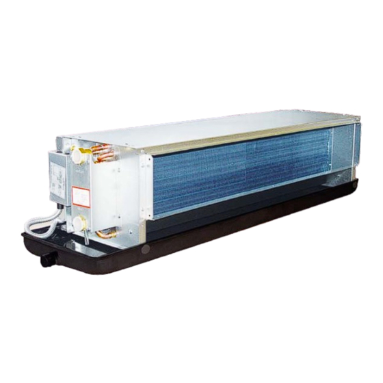
Ducted Type Fan Coil Unit
Table of
Contents
Previous
Page
Next
Page
1
2
3
4
5
Advertisement
Table of Contents
Need help?
Do you have a question about the FCR and is the answer not in the manual?
Ask a question
Questions and answers
Related Manuals for Sakura FCR
Air Conditioner Sakura FFM User Manual
Ducted type fan coil unit (145 pages)
Air Conditioner Sakura FASN 080-600 Installation, Operaton & Maintenance Manual
Air-cooled split ducted air conditioner (20 pages)
Air Conditioner Sakura FVCA Series Installation, Operation And Maintenance Manual
Air cooled mini chiller (19 pages)
Air Conditioner Sakura COOLING ONLY Installation, Operation & Maintenance Manual
Rooftop package air conditioner (24 pages)
Air Conditioner SAKURA HBK-18?23DS Operation / Installation / Service Manual
Evaporative air cooler, lcd wall-pad remote controller, hand-held remote controller (16 pages)
Air Conditioner Sakura HBK-23DL Operation / Installation / Service Manual
Evaporative air cooler (17 pages)
Air Conditioner Sakura SFP-KM-DLY Series Installation Manual
Hydronic cassette sfp-km-dly series; (73 pages)
Air Conditioner Sakura SRT-30RA Installation Manual
Rooftop package air conditioner (17 pages)
Air Conditioner Sakura SFP KM EC Series Technical Installation Manual
Hydronic cassette (47 pages)
This manual is also suitable for:
Fcrd
Ffr
Ffm
Fcrt
Table of Contents
Print
Rename the bookmark
Delete bookmark?
Delete from my manuals?
Login
Sign In
OR
Sign in with Facebook
Sign in with Google
Upload manual
Upload from disk
Upload from URL


Need help?
Do you have a question about the FCR and is the answer not in the manual?
Questions and answers