Table of Contents
Advertisement
INSTALLATION AND SERVICE MANUAL
TWO VALVE DISPENSER
Part Number 85-3322
Part Number 85-3332
This manual supersedes and replaces 28-0703, dated 05/24/06
• NORTH AMERICA – 210-310-7245 • INTERNATIONAL SALES – 210-310-7242 • CUSTOMER SERVICE – 210-310-7242 •
• LATIN AMERICA – 210-310-7245 • EUROPE – 32-2-755-2399 • PACIFIC – 61-8-8268-1978 •
"Lancer" is the registered trademark of Lancer • Copyright — 2006 by Lancer, all rights reserved
Please refer to the Lancer web site (www.lancercorp.com) for information relating to Lancer
Installation and Service Manuals, Instruction Sheets, Technical Bulletins, Service Bulletins, etc.
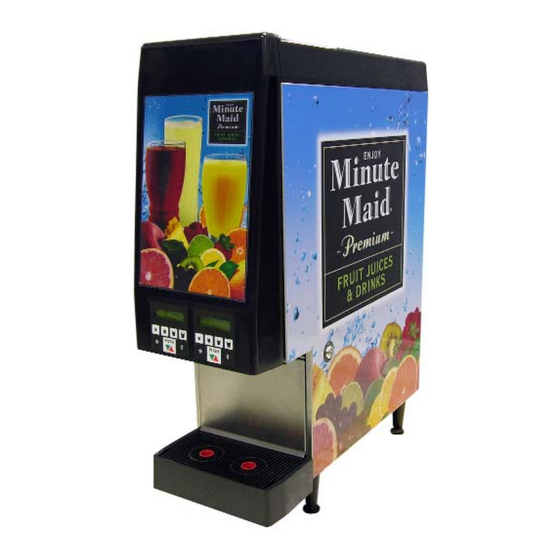
MINUTE MAID JUICER
Two Valve, Push Control
Two Valve, Portion Control
6655 LANCER BLVD. • SAN ANTONIO, TEXAS 78219 USA • (210) 310-7000
FAX SALES
FAX Engineering: • 210-310-7096
FOR
115V/60 Hz
115V/60 Hz
DATE:
08/23/06
P.N.
28–0703/01
Advertisement
Table of Contents

Related Manuals for lancer 85-3322

Summary of Contents for lancer 85-3322
- Page 1 • NORTH AMERICA – 210-310-7245 • INTERNATIONAL SALES – 210-310-7242 • CUSTOMER SERVICE – 210-310-7242 • • LATIN AMERICA – 210-310-7245 • EUROPE – 32-2-755-2399 • PACIFIC – 61-8-8268-1978 • FAX Engineering: • 210-310-7096 DATE: 08/23/06 P.N. 28–0703/01 "Lancer" is the registered trademark of Lancer • Copyright — 2006 by Lancer, all rights reserved...
-
Page 2: Table Of Contents
TABLE OF CONTENTS TABLE OF CONTENTS ............................i ACCESSORIES FOR MINUTE MAID JUICER ....................ii SPECIFICATIONS..............................ii 1. INSTALLATION ............................1 RECEIVING............................1 UNPACKING ............................1 SELECTING COUNTER LOCATION ....................1 FILLING THE UNIT WITH WATER ....................1 CONNECTING THE WATER SUPPLY ....................2 CONNECTING THE ELECTRICAL POWER ..................2 KEY LOCK SWITCH ..........................2 INSTALLING THE CONCENTRATE PACKAGES................2 PURGING THE WATER SYSTEM OF AIR ..................2... -
Page 3: Table Of Contents
TABLE OF CONTENTS (CONTINUED) DOOR STRUTS/TRIM ASSEMBLY ....................23 ELECTRICAL COMPONENT, DETAIL .....................24 CABINET ASSEMBLY ........................25 PERIPHERAL COMPONENTS/FINAL ASSEMBLY.................26 UNPACKING DETAIL ........................27 FLOW METER/SOLENOID ASSEMBLY..................28 7.10 COMPRESSOR DECK ASSEMBLY ...................29-30 7.11 LEFT DOOR ASSEMBLY (TYPICAL) ..................31-32 7.12 TOP COVER ASSEMBLY, DETAIL ....................33 7.13 ASSEMBLED UNIT ..........................34 7.14 WATER FLOW DIAGRAM........................35 7.15 WIRING DIAGRAM ..........................36... -
Page 4: Installation
1. INSTALLATION RECEIVING Each shipment is completely tested under operating conditions and thoroughly inspected before shipment. At time of shipment, the carrier accepts the Unit and any claim for damage must be made with the carrier. Upon receiving Unit from the delivering carrier, carefully inspect carton for visible indication(s) of damage. -
Page 5: Connecting The Water Supply
E. Lubricate the O-rings on the fitting with Lancer Lube and insert into the 1/4 turn shutoff valve and secure with sliding clip. (On installations going through the back of the wrapper, remove the cover plate on the back of the Unit and thread the tubing through the lower section of the machine and out the back of the Unit.) -
Page 6: Operating The Unit
2. OPERATING THE UNIT PRODUCT LOADING/UNLOADING A. Thaw the Minute Pak in a 40 degree ® F cooler for 48-72 hours. B. Shake the Minute Pak well (see ® Figure 1). Figure 1 C. Turn unit to “Flush Mode” (key on right bottom side of dispenser) (see Figure 2). -
Page 7: Sold Out Operations
SOLD OUT OPERATIONS A. When the display shows SOLD OUT or CHANGE PRODUCT, follow the loading procedures to change the package. B. Once the package is changed, touch the * in the bottom left hand corner of each touch pad affected until concentrate pours (see Figure 7). - Page 8 D. Check/Adjust Ratios 1. To check and/or adjust the ratio you measure the amount of water dispensed and then the finished product dispensed into a graduated cylinder. You adjust the finished product to equal the volume of water dispensed. 2. Process a.
-
Page 9: Dispensing Configurations
H. If out of spec (finished product volume does not equal water volume), adjust the ratio by pushing the * and # buttons: For example: 1. If the ratio is 4 bands below, toggle down to -4 using the * and # buttons (see Figure 13). Press pour cancel and check volume again - Repeat until correct. -
Page 10: Cleaning And Sanitizing Instructions
G. Follow the same procedures to set the fill volume for the remaining valves. NOTE Since the volume settings are unique to each valve, each valve can have four different dispense volumes. Lemonade in valve position 1, for example, could have a different dispense volume (i.e., “SMALL”... -
Page 11: Operating Principles
6. Replace check valve in sanitizing container. 7. Activate “PURGE BUTTON” for two (2) minutes ensuring concentrate lines are full of solution. Let solution stand for five (5) minutes without dispensing. 8. For each valve, perform a second two (2) minute dispense and let stand for an additional five (5) minutes. -
Page 12: Electrical System
would not restart immediately when power is re-established. There is a restart delay circuit [approximately five (5) minutes] built into the ice bank control to prevent the compressor from starting under pressure. This feature protects the compressor from premature failure. The unit has a “lift out”... -
Page 13: Relocating Or Shipping Unit
4. RELOCATING OR SHIPPING UNIT REMOVING AN OPERATING UNIT A. Remove concentrate packages (see Section 2.1). B. Turn water supply OFF at the source. Activate one of the valves to drain the water from the system. C. Remove the splash plate. Slide the locking clip on the Shut Off Valve to release the inlet fitting and remove the inlet fitting from the valve, leaving the valve connected to the unit. -
Page 14: Door Disassembly
the graphic insert and backing plate are in position and have not slipped down. If this occurs, the lens will bind at the top and could break the top tabs. H. Open door and turn lens release handles to the locked position. DOOR DISASSEMBLY 5.2.1 DOOR REMOVAL A. -
Page 15: Gas Strut Replacement
C. Slowly work the remaining sections of the gasket until the gasket is completely seated. 5.2.6 GAS STRUT REPLACEMENT A. Open door. B. Gently push upward on the door to relieve the door’s weight from the gas spring and slide the pin out of the clevis that anchors the gas spring to the door. -
Page 16: Product Recognition/Sold Out Sensors Removal
C. Remove the four screws that secure the deck to the insulated tank assembly (a 3/8” socket and a long extension are required). D. Unplug the main power harness from the ice bank control box. E. Locate a suitable location to place the deck once it is removed, considering that the melting ice will allow the deck to slide easily and make a mess. -
Page 17: Nozzle Replacement
Slide the two retainers on the top and bottom of the water calibrations valve assembly to the “disengage” position. J. Push the water calibrations valve assembly down until the outlet connector tube telescopes into the base of the unit. K. While holding the outlet connector tube, lift up on the water calibrations valve assembly to disengage it from the outlet connector tube. -
Page 18: Wrapper Removal
B. Turn key switch to OFF position. C. Remove nozzle by “wiggling” it out of the water fitting and concentrate delivery tube. D. Remove both the left and right platform base. E. Remove the thumb screws that secure the pump assembly platform base to the cabinet. F. -
Page 19: Dispensing System
TROUBLE CAUSE REMEDY Compressor will not run. A. Unit not connected to A. Connect unit power cord to electrical outlet. electrical outlet. B. Power supply electrical B. Reset circuit breaker or replace Note: breaker tripped or fuse blown. fuse. If problem persists: The ice bank controller 1. - Page 20 working parts, such as driver boards, from one side of the dispenser to the other side of the dispenser. Similarly, the right and left door harnesses can be swapped at the electronic control box to aid in trouble-shooting door problems. Before troubleshooting a problem with the Electronic Control System, first perform a few initial tests to aid in diagnosing the problem.
- Page 21 TROUBLE CAUSE REMEDY Brix too low. A. Pump Cavitator. A. Probably caused by inserting a frozen solid package. (Although temperature of the product does not have to be 40 F. for the dispenser to operate properly, the product must at least be in liquid form.) B.
-
Page 22: Illustrations, Parts Listings, Wiring And Water Flow Diagrams
7. ILLUSTRATIONS, PARTS LISTINGS, WIRING, AND WATER FLOW DIAGRAMS FRAME/INSULATION TANK ASSEMBLY Item Part No. Description 50-0453 Insulation, Tank, Strip 82-3662 Tank Assy 04-0220 51-6102 Frame Assy 01-0789 02-0005 O-Ring 02-0110 Umbrella Check Valve 17-0408 Vacuum Breaker Assy (Includes Items 5-8) -
Page 23: Insulated Tank Assembly
INSULATED TANK ASSEMBLY Item Part No. Description 47-1539 Tube, Water Coil 01-0797 Nut Assy 48-1161 Tube Assy, Manifold, Water 02-0155 O-Ring 48-1058 Tube Assy, Interface, Water OUT 48-1166 Tube Assy, Water IN 19-0422 Valve Assy, Water, Calibration 02-0371 Flow Washer 02-0089 O-Ring 48-1162... -
Page 24: Pump Platforms/Fan Plate Assembly
PUMP PLATFORMS/FAN PLATE ASSEMBLY... - Page 25 PUMP PLATFORMS/FAN PLATE ASSEMBLY (CONTINUED) Item Part No. Description 81-0650 Fan Assy, Pump Housing, FCOJ 04-0741 Screw, 6 - 32 x 0.375, Pan Hd 04-0238 Screw, 8 - 16 x 0.375, PHP, Pan Hd 309658 Plate, Product Support, FCOJ 01-2042 Water Connector, Compass 02-0005 O-Ring, 2-010...
-
Page 26: Door Struts/Trim Assembly
DOOR STRUTS/TRIM ASSEMBLY Item Part No. Description 05-1035 Funnel, Wire 04-0470 Screw, 6 - 19 x 0.500, Pan Hd 05-1058 Bracket, Upper 81-0307 Pin, Door, Clevis 81-0405 Gas Spring, 30 Pound 04-0788 Screw, 6 - 32 x 0.438, Binder Hd 05-1224 Door Frame 05-2416... -
Page 27: Electrical Component, Detail
ELECTRICAL COMPONENT, DETAIL Item Part No. Description 82-3706 Deck Assy, Refrig., 115V/60Hz 04-0740 Screw, 1/4 - 20 x 1.000, Hex Hd with Washer 08-0315 Tube, Drain, Front 02-0047 O-Ring 82-3717 Cover, Control Box, CPU, FCOJ 82-1832 Evaporator Coil Assy... -
Page 28: Cabinet Assembly
CABINET ASSEMBLY Item Part No. Description 04-0750 Screw, 6 - 32 x 2.812, Pan Hd 82-3707 Top Cover Assy 04-0788 Screw, 6 - 32 x 0.438, Binder Hd 04-0741 Screw, 6 - 32 x 0.375, Pan Hd 52-1668 Key Switch Assy 82-3762 Wrapper Assy 04-0792... -
Page 29: Peripheral Components/Final Assembly
PERIPHERAL COMPONENTS/FINAL ASSEMBLY Item Part No. Description 82-3696 Door Assy, FCOJ, 2V 54-0420 Grill, Drip Tray 04-0591 Screw, 6 - 19 x 0.563, Flat Hd, Plastite 02-0409 Seal, Spout 81-0405 Spring, Gas, 30# 82-3789 Drop-Cup-Rest Assy 04-0477 Screw, 8 - 32 x 0.375, Pan Hd, ROLOK 05-1284 Drip Tray with Drain... -
Page 30: Unpacking Detail
UNPACKING DETAIL Item Part No. Description 04-0203 Screw, 0.375-16 x 1.000, Flat Hd 90-1310 Shipping Board 07-0211 Washer... -
Page 31: Flow Meter/Solenoid Assembly
FLOW METER/SOLENOID ASSEMBLY Item Part No. Description 04-0716 Screw, 6 - 19 x 1.862, Pan Head 05-0707 Retainer, Soda Solenoid 10-0269 Plug, Nut, Solenoid 02-0089 O-Ring 81-0407 Bonnet, Solenoid, Nickel Plated 04-0820 Washer, Solenoid 02-0354 O-Ring 04-0549 Screw, 6 - 19 x 0.625, Pan Head 04-0270 Screw, 6 - 19 x 0.910, PHD, PH/SL. -
Page 32: Compressor Deck Assembly
7.10 COMPRESSOR DECK ASSEMBLY... - Page 33 7.10 COMPRESSOR DECK ASSEMBLY (CONTINUED) Item Part No. Description 30-9580 Plate, Agitator, Premia 50-0454 Insulation, Refrigeration Deck 82-1832 Evaporator Coil Assy 23-1052 Condenser 30-6371 Shroud, Fan 04-0504 Screw, 8 - 18 x 0.375 52-3020 Motor, Fan, 115V 23-1406 Grill, Condensor Fan 04-1512 Screw, 6 - 32 x 1.875, Pan Head 52-1882-01...
-
Page 34: Left Door Assembly (Typical)
7.11 DOOR ASSEMBLY... - Page 35 7.11 DOOR ASSEMBLY (CONTINUED) Item Part No. Description 02-0417 Seal, Door, Premia 04-0470 Screw, 6 - 19 x 0.500, PH 04-0135 Screw, 6 - 32 x 0.312, PH 05-1021 Hinge, Door, Premia 24-0031 Latch Assy, Door 05-0716 Clevis, Door, ITA, Premia 04-0789 Screw, 6 - 32 x 0.500, BH 04-0746/01...
-
Page 36: Top Cover Assembly, Detail
7.12 TOP COVER ASSEMBLY, DETAIL Item Part No. Description 54-0226 Top Cover, Sub-Assy 05-1019 Cover, Hinge, LH 05-1018 Cover, Hinge, RH 82-1523 Hinge Pin Assy, Left 82-1524 Hinge Pin Assy, Right 04-0135 Screw, 6 - 32 x 0.312, Pan Head 30-6346 Grid, Cover, Top 04-0747... -
Page 37: Assembled Unit
7.13 ASSEMBLED UNIT... -
Page 38: Water Flow Diagram
7.14 WATER FLOW DIAGRAM FOAMED TANK ASSEMBLY BALL VALVE WATER IN WATER COIL ASSEMBLY UMBRELLA FOAMED TANK ASSEMBLY CHECK VALVE & & VALVE 2 VALVE 1 BASE ASSEMBLY NOTE: WATER OUT WATER OUT 1. " " DENOTES SLIP FIT O-RING CONNECTION POINT. -
Page 39: Wiring Diagram
7.15 WIRING DIAGRAM PWR SUPPLY BD AGITATOR DECK AC IN BOX FAN CIRCUIT CAB FAN BREAKER KEY SW DR BD LT BD REAR S/O DISPLAY DOOR SOLENOID... - Page 40 NOTES Please refer to the Lancer web site (www.lancercorp.com) for information relating to Lancer Installation and Service Manuals, Instruction Sheets, Technical Bulletins, Service Bulletins, etc.
Need help?
Do you have a question about the 85-3322 and is the answer not in the manual?
Questions and answers