Table of Contents
Advertisement
Quick Links
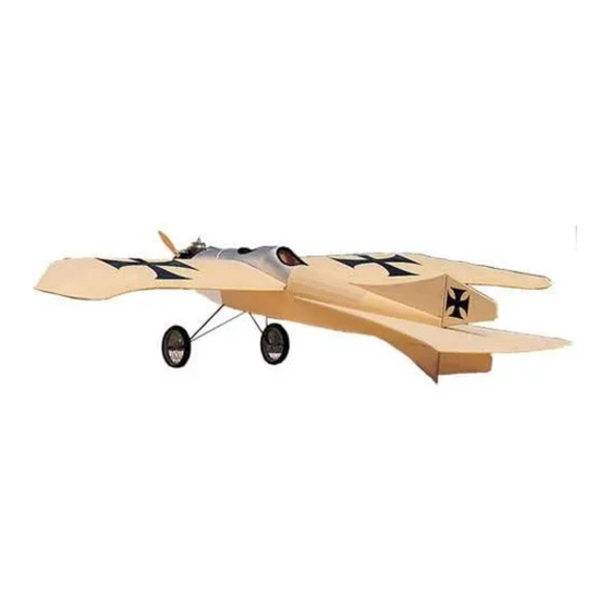
TAUBE 40
Read through the instruction manual first to familiarize yourself with the type of construction
used in this model. The manual also contains important warnings and instructions for the
assembly and the use of this model. Balsa USA's only obligation shall be to replace such
quantity of the product to be defective. User shall determine the suitability of the product for
the intended use and shall assume all risk and liability in connection therewith.
BALSA USA KIT GUARANTEE
We at Balsa USA want you to be completely satisfied with
your kit purchase. If for any reason you are not satisfied with
any part in the kit you purchased, either from us or one of our
authorized hobby dealers, we will replace the part(s) in
question immediately. If you have any questions regarding
the construction of the model or any technical questions
regarding the kit, please call us on our customer service line.
One of our technical representatives will be happy to help
you.
Assembly Manual
Made in the USA
BALSA USA
P.O. Box 164
Marinette, WI 54143
(906) 863-6421
© Copyright 1997
Advertisement
Table of Contents

Related Manuals for Balsa Taube 40

Summary of Contents for Balsa Taube 40
- Page 1 The manual also contains important warnings and instructions for the assembly and the use of this model. Balsa USA’s only obligation shall be to replace such quantity of the product to be defective. User shall determine the suitability of the product for the intended use and shall assume all risk and liability in connection therewith.
-
Page 2: Building Instructions
It is the buyer’s complete responsibility to assemble the model correctly, properly install the engine, Thank you for purchasing our completely new Taube 40 kit. radio, and all other equipment required to operate the A lot more has changed than just this new instruction model. -
Page 3: Key To Abbreviations
The Taube is built using balsa, spruce, birch plywood, lite When drilling holes in balsa, it is best to use a pin vise to (poplar) plywood, and basswood. Each of these woods have hold the drill bit rather than chuck it up in an electric drill. - Page 4 It is not difficult to remove cured CA from the skin or to part Adhesives bonded skin. When this happens, it is best to use Balsa USA Un- Stik-It debonder to dissolve the cured CA. If this is not available, If Balsa USA Gold CA products are used for the construction of you can also use an acetone based fingernail polish remover.
- Page 5 Key to Die Cut Parts Fuse Sides (2) Balsa Sheets Required - 1/8 x 3-5/8 x 39 Wing Tip TE Wing Tip TE Trailing Edge (4) Balsa Sheets Required - 1/8 x 3 x 30 Rear Dihedral Brace F-2A Front Dihedral...
- Page 6 Key to Die Cut Parts Main Rib Main Half Rib Main Rib Main Leading Edge Corners Half Rib (6) Balsa Sheet - 1/8 x 3 x 12 F-2B Aft Deck Former Aft Deck Former F-3C Aft Deck Former (1) Balsa Sheet - 1/8 x 3 x 21...
- Page 7 1.) Start by covering the plan with wax paper or Saran™ Wrap. 2.) Cut the lower forward 1/4 x 3/8 x 24 balsa spars to length. Note that they end just inside of the second tip rib. Pin the spars in place on both right and left panels.
- Page 8 16.) Refer to Photo 10. Fit and glue in place the last two W-4 and PHOTO 7 W-5 tip ribs and the two false ribs. PHOTO 11 11.) Glue all (10) main false ribs in place. PHOTO 8 PHOTO 12 17.) Locate the four diecut leading edge pieces, two long and two short.
- Page 9 PHOTO 19 PHOTO 15 21.) Use the 1/4 x 1/4 x 15 for the upper wingtip spar. Cut the 24.) Remove one wing panel from your building board. Block angle at the front of the spar so it will fit flush against the back the wing up so it is 1-1/4”...
- Page 10 30.) Sheet the next two pieces of center section using 3/32 x 3 x as outlined in the drawing below. This will give you a nice even 12 balsa. Note that the ribs at the trailing edge may have to be radius all along the part and makes it easy to do.
-
Page 11: Fuselage Construction
1/8” wide at the front end of the stab. 1.) Cut the 1/4 x 5/8 balsa strips to length. Note that both ends of Do both sides and then trim the excess off to your lines. - Page 12 Keep America Beautiful - in place. This runs from the front line drawn up by the firewall, ahead of former F-2 to the tailpost. From now until assembling the fuse sides together, perform all steps for both fuse sides. Fly Balsa USA Kits...
- Page 13 PHOTO 43 PHOTO 40 10.) Refer to Photo 40. Mark the centers on the tops of formers F-2, F-3, and F-4. Note that F-2 is marked at the top of the upper longeron. PHOTO 41 PHOTO 44 15.) Taper the upper and lower longerons and the 1/4” square strip as shown above and on the top view of the fuselage plan.
- Page 14 You just want to smooth the saddle. PHOTO 51 20.) Use the 1/8 x 3 x 30 balsa to sheet the bottom of the fuse from the LG block aft. Use the 1/8 x 3 x 10 to sheet from the LG block forward.
- Page 15 F4A behind it. shape of the fuselage itself. Different sheets of balsa may bend differently. This may require you to adjust the formers slightly for PHOTO 57 a perfect fit in this location.
- Page 16 PHOTO 62 44.) Cut the 1/8 x 1/8 x 30 balsa strip to fit between formers F- PHOTO 59 3A and F-3C as shown above. Be sure the strip is flush with the outside edge of the formers.
- Page 17 PHOTO 64 PHOTO 67 48.) This is going to be a tough step. Use a nickel to draw a circle around the wing bolt holes. Now cut the wing sheeting out to the 51.) Holding the sheeting in place, place a pin both fore and aft lines to allow the wing bolts to pass through.
- Page 18 2.) Measure back 4-5/8” and glue the next largest one in place. The last deck former is diecut into two pieces. 3.) Cut a 1/4” square balsa cross piece and glue it in place about 1” behind the last former. Slide a piece of 1/4” stock into the stabilizer slot to keep the slot 1/4”...
- Page 19 PHOTO 75 6.) Cut and glue in place the 3/16 x 1/4 x 6 balsa strip from former F-4A to the fin. Make sure it is centered on the fin. 7.) Cut to length and glue a 3/16 x 3/16 x 10 balsa strip right alongside the 3/16 x 1/4 piece.
- Page 20 PHOTO 83 Finishing the Model 1.) Refer to the tip on installing control horns. Mount the elevator and rudder control horns. Note that they should be on opposite sides of the model so they won’t touch into each other when the model is finished.
-
Page 21: Balancing The Model
PHOTO 87 PHOTO 90 5.) Fit and glue in place the 1/8” balsa nose piece. 13.) Bend the 3/32”music wire tail skid to shape as shown on the plan. Drill the sub-fin with a 3/32” drill bit and glue the wire in PHOTO 88 place. -
Page 22: Control Surface Throws
Now we are finally getting to the good part! You will find that the Taube 40 will be one of the easiest and most relaxing models that Thanks again for purchasing our products. you have flown in a long time. However, before we get down to the flying you need to go over your model one last time to make sure that everything is as it should be.
Need help?
Do you have a question about the Taube 40 and is the answer not in the manual?
Questions and answers