Table of Contents
Advertisement
Model SS-158 EDX(B)
Service Manual
T X / R X
V O L
S Q
M IC G A IN
R F G A IN
O FF
O FF
SS-158EDX(B)
H I
L O
T .B .
FR EQ U EN C Y C O U N T ER
O FF
E-T O N E
A M
I/ C
J / D
FM
U S B
H / B
K / E
C W
G / A
L / F
B A N D
©
N B / A N L
R .B .
O FF
O FF
S W R
+ 1 0 K H z
S / R F
O FF
FIN E
C O A R S E
L S B
+
S S -1 5 8 ED X
Advertisement
Table of Contents

Related Manuals for Super Star SS-158EDX


Summary of Contents for Super Star SS-158EDX
- Page 1 C O A R S E I/ C J / D U S B H / B K / E L S B G / A L / F O FF O FF S S -1 5 8 ED X B A N D SS-158EDX(B)...
- Page 2 TABLE OF CONTENTS PAGE CHAPTER 1 Specifications ........1.0 General .
-
Page 3: Chapter 1 Specifications
CHAPTER 1 SPECIFICATIONS 1.0 GENERAL Model SS-158EDX Channels 480FM, 480AM, 480LSB, 480USB, Frequency Range 28.245 ~ 29.655 MHz Frequency Control Phase-Lock-loop (PLL) Synthesizer Frequency Stability 0.001% Temperature Range -30°C to +50°C Antenna Impedance 50 Ohms Antenna Connectors Standard SO-239 type Input Voltage 13.8V DC... -
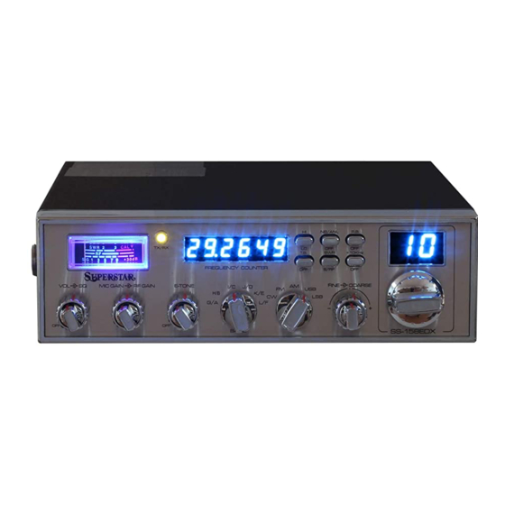
Page 4: Front Panel
CHAPTER 2 OPERATION 2.0 FRONT PANEL 13 14 15 16 17 18 19 N B / A N L R .B . T X / R X O FF O FF T .B . S W R + 1 0 K H z FR EQ U EN C Y C O U N T ER O FF S / R F... - Page 5 7. MODE CONTROL : This control allows you to select one of the following operating modes : CW/FM/AM/USB/LSB. 8. FINE/COARSE CONTROL : Allows variation of the receive operating frequency above or below the assigned frequency. Although this control is intended primarily to tune in SSB/CW signals, it may be used to optimize AM/FM signals as described in the Operating Procedure paragraphs.
-
Page 6: Rear Panel
2.1 REAR PANEL ANT. PA.SP. EXT.SP. CW.KEY POWER 1. ANTENNA : This jack accepts 50 ohms coaxial cable with a PL-259 type plug. 2. DC POWER : This accepts 13.8V DC power cable with built-in fuse. The power cord provided with the radio has a black and red wire. -
Page 7: Procedure To Receive And Transmit
PROCEDURE TO RECEIVE AND TRANSMIT A. MICROPHONE The receiver and transmitter are controlled by the push-to-talk switch on the microphone. Press the switch and the transmitter is activated, release switch to receive. When transmitting, hold the microphone two inches from the mouth and speak clearly in a normal voice. This transceiver comes complete with a low impedance dynamic microphone. -
Page 8: Receiving Ssb Signals
RECEIVING SSB SIGNALS There are four types of signals presently used for communications in the Citizens Band : FM, AM, USB and LSB. When the MODE switch on your unit is placed in the AM position, only standard double-side band and in FM position, only frequency deviation, full carrier signals will be detected. - Page 9 Once the desired SSB mode has been selected, frequency adjustment may be necessary in order to make the incoming signal intelligible. The FINE/COARSE control allows the operator to vary frequency above or below the exact frequency of the channel. If the sound of the incoming signal is high or low pitched, adjust the operation of the FINE/COARSE. Consider it as performing the same function as a phonograph speed control.
-
Page 10: Alternate Microphones And Installation
ALTERNATE MICROPHONES AND INSTALLATION For best results, the user should select a low-impedance dynamic type microphone or a transistorized microphone. Transistorized type microphones have low output impedance characteristics. The microphones must be provided with a four-lead cable. The audio conductor and its shielded lead comprise two of the leads. The third lead is for transmit control and fourth is for receiving control. - Page 11 the connections. Keep the exposed wire lengths to a minimum to avoid shorting when the microphone plug is reassembled. Fig. 2 Microphone plug wiring To wire the microphone cable to the plug provided, proceed as follows : 1. Remove the retaining screw. 2.
- Page 12 Fig. 3 Microphone plug pin numbers viewed from rear of pin receptacle. 6. Be sure that the housing and the knurled ring of Figure 2 are pushed back onto the microphone cable before starting to solder. If the washer is not captive to the pin receptacle body, make sure that it is placed on the threaded portion of the pin receptacle body before soldering.
- Page 13 CIRCUIT DESCRIPTION CHAPTER 3 3.0 INTRODUCTION This section explains the technical theory of operation for the SS-158 EDX mobile AMATEUR radio. 3.1 PLL CIRCUIT The Phase Lock Loop (PLL) circuit is responsible for developing the receiver’s first local oscillator signal and the transmitter’s exciter signal. The PLL circuit consists primarily of IC2, IC3, IC4, IC5, Q25, Q27, Q28 and Q29.
- Page 14 3.4 TRANSMITTER AMPLIFIER CIRCUIT The transmitter takes the basic exciter signal from IC9 of the TX mixer and amplifies it through a series of amplifiers consisting of Q52, Q51, Q49 ,Q47and Q48 where it is sent out to the antenna connector.
- Page 16 ALIGNMENT CHAPTER 4 4.0 REQUIRED TEST EQUIPMENT DC Power Supply (13.8VDC, 10A) Frequency Counter (100 MHz) RF Wattmeter (10W) RF Signal Generator (100 MHz) Multi-meter Automatic Distortion Meter Automatic Modulation Meter Oscilloscope (50 MHz) Audio Signal Generator Sinad Meter 4.1 ALIGNMENT PROCEDURES This transceiver has been aligned at the factory and does not require any adjustments at installation.
- Page 17 ADJUST ITEM U.U.T. SETTING MEASUREMENT POINT Set radio to CH 1 BAND A USB RX mode. 13.5725MHz ± 20Hz Frequency Connect Frequency Counter to TP3. Set radio to CH 1 BAND G USB RX mode. 16.2675MHz ± 20Hz Frequency Connect Frequency Counter to TP3. Set radio to CH 1 BAND A USB RX mode.
- Page 18 ADJUST ITEM U.U.T. SETTING MEASUREMENT POINT SSB APC Set radio to CH 19 USB RX mode. VR17 12.5 VDC Connect Multi-meter to TP7. SSB TX Power Connect “short PCB” to TP7 and TP9. L40,L42, MAX > 28W Connect RF Power Meter to antenna jack. L43,L44 Spurious Emission Set radio to CH 1 BAND G USB TX mode.
- Page 19 4.1.3 RECEIVER ALIGNMENT ADJUST ITEM U.U.T. SETTING MEASUREMENT POINT AM Sensitivity Set radio to CH 40 BAND F RX mode. Set RF GAIN Fully Clockwise. L2,L3,L5,L6, Audio Output > 2V Set SQ Fully Counter Clockwise. L7,L8,L9,L10 S/N > 10 dB. Set VOL Control at 2 o’clock.
- Page 20 ADJUST ITEM U.U.T. SETTING MEASUREMENT POINT AM S-Meter Set radio to CH 40 BAND F AM RX mode. For a reading of “9” RF SG setting 26.955 MHz, 100uV. Mod 30%. VR1 on the “S” scale. SSB S-Meter Set radio to CH 19 USB RX mode. RF SG setting 26.966 MHz, 100uV.
- Page 21 Figure 4.1.2 Transmitter test setup Figure 4.1.3 Receiver test setup - 20 -...
- Page 22 SS-158EDX(B) MAIN PCB ADJUSTMENT LOCATION - 21 -...
- Page 23 CHAPTER 5 MAINTENANCE 5.0 PRECAUTIONS The inherent quality of the solid-state components used in this transceiver will provide many years of continuous use. Taking the following precautions will prevent damage to the transceiver. (i) Never key the transmitter unless an antenna or suitable dummy load is connected to the antenna receptacle.
- Page 24 CHAPTER 6 DIAGRAMS & PARTS LIST 6.0 GENERAL Information on most electrical and mechanical parts is included in the parts list. The reference designators are in alphanumeric order. - 23 -...
- Page 25 SS-158 EDX(B) DISPLAY PCB (EPT900022Z) (COPPER SIDE) ( COMPONENT SIDE ) - 24 -...
- Page 26 PART LIST: SS-158 EDX(B) DISPLAY P.C.B REFERENCE RANGER PART ITEM DESCRIPTION NUMBER NUMBER EPT90022Z DISPLAY PCB CHANNEL DISPLAY EX03N40521 LED DISPLAY COUNTER DISPLAY EX03N40516 BLUE LED DISPLAY TX/RX LED EX01N40004 RED/GREEN LED EWPS33033X PUSH SW TALKBACK ,HI/LOW, S-RF/SWR, NB/ANL/OFF, ROGER BEEP, +10KHz CN1,CN2 EX07N48928 PCB CONNECTOR/S 12P...
- Page 27 SS-158 ( B) EDX ROTARY SWITCH PCB (EPT900030Z) ( COMPONENT SIDE ) (COPPER SIDE) PART LIST: SS-158 EDX(B) ROTARY SWITCH P.C.B REFERENCE RANGER PART ITEM DESCRIPTION NUMBER NUMBER EPT900030Z R315(BLUE) RCP161024Z 1K OHM 1/16W P R312,313,314,316-324(B RCP161524Z 1.5K OHM 1/16W P LUE) J303,304,305,306 WX01070705...
- Page 28 SS-158(B) EDX COUNTER PCB (EPT900043Z) ( COMPONENT SIDE ) - 27 -...
- Page 29 (COPPER SIDE) - 28 -...
- Page 30 PART LIST: SS-158 EDX(B) COUNTER P.C.B REFERENCE RANGER PART ITEM DESCRIPTION NUMBER NUMBER EPT900043Z COUNTER P.C.B R2,16 RCY014704Z 47 OHM 0.1W RCY011014Z 100 OHM 0.1W R10,29,30,31,32,33,34,3 RCY012214Z 220 OHM 0.1W 5,36,37,38,39,40,41 R18,21-41 RCY013314Z 330 OHM 0.1W R14,46 RCY011024Z 1K OHM 0.1W(0805) RCY012724Z 2.7K OHM 0.1W R4,5...
- Page 31 SS-158(B) VR PCB (EPT690070A) ( COMPONENT SIDE ) (COPPER SIDE) PART LIST: SS-158 EDX(B) VR P.C.B REFERENCE RANGER PART ITEM DESCRIPTION NUMBER NUMBER VR PCB EPT690070A RCP161024Z 1K OHM 1/16W P J1,5 EX07N48223 2P PH=2MM EX07N48350 3P PH=2MM EX07W48824 3P PH=2MM EX07W48826 5P PH=2MM EX07N48331...
- Page 32 SS-158(B) ANT PCB (EPT360042Z) ( COMPONENT SIDE ) (COPPER SIDE) - 31 -...
- Page 33 PART LIST: SS-158 EDX(B) ANT P.C.B REFERENCE RANGER PART ITEM DESCRIPTION NUMBER NUMBER EPT360042Z ANT PCB RCY010004Z 0 OHM 0.1W RCY014714Z 470 OHM 0.1W R3,4 RCY011014Z 100 OHM 0.1W RCY013314Z 330 OHM 0.1W R5,11 RCY011024Z 1K OHM 0.1W(0805) R10,12 RCY012224Z 2.2K OHM 0.1W(0805) R7,C5 RCY011034Z...
- Page 34 SS-158(B) MIC PCB (EPT690050Z) ( COMPONENT SIDE ) ( COPPER SIDE ) PART LIST: SS-158 EDX(B) MIC P.C.B REFERENCE RANGER PART ITEM DESCRIPTION NUMBER NUMBER EPT6900050Z MIC PCB C502,503,504,501 CC0501027L 0.001UF 50WV SL Z C505,506 CC0501037L 0.01UF 50WV SL Z Q501 TDTA0124ES DTA124ES...
- Page 35 SS-158(B)ECHO PCB (EPT0SSB50I) ( COMPONENT SIDE ) ( COPPER SIDE ) - 34 -...
- Page 36 PART LIST: SS-158 EDX(B) ECHO P.C.B REFERENCE RANGER PART ITEM DESCRIPTION NUMBER NUMBER EPT0SSB50I ECHO PCB RCM1610048 10 OHM 1/16W RCM1610145 100 OHM 1/16W RCM1610245 1K OHM 1/16 W R7,16,26 RCM1622245 2.2K OHM 1/16W R29,30 RCM1647245 4.7K OHM 1/16W R22,23,24,32 RCM1610345 10K OHM 1/16W R5,18,28...
- Page 37 REFERENCE RANGER PART ITEM DESCRIPTION NUMBER NUMBER EEX07N41266 6P T JP1,3,4,6,7 WX01070705 7x5x7 JP2,5 WX01070708 7x8x7 - 36 -...
- Page 38 SS-158(B)MAIN PCB (EPT690010D) ( COMPONENT SIDE ) - 37 -...
- Page 39 ( COPPER SIDE ) - 38 -...
- Page 40 PART LIST: SS-158 EDX(B) MAIN P.C.B REFERENCE RANGER DESCRIPTION REFERENCE RANGER DESCRIPTION NUMBER PART NO. NUMBER PART NO. R36,67,98,115,116,27 RCM1610245 1K OHM 1/16 W M EPT690010D MAIN PCB 0,271,118,123,136-138 ,143,144,154-156,160, R258 RCP160004Z 0 OHM 1/16W P 164,166,167,179,186,2 R246 RCM1647945 4.7OHM 1/16W 05,206,214,217,303,23 2,240,261,292,295,291 R267...
- Page 41 REFERENCE RANGER DESCRIPTION REFERENCE RANGER DESCRIPTION NUMBER PART NO. NUMBER PART NO. R7,29,61,63,96,126,14 RCM1647345 47K OHM RCM1668148 680 OHM 1/16W 9-151,157,185,236,224 1/16W RCM1668345 68K OHM R62,64,72,237,238 RCM1610248 1K OHM 1/16W R21,85,105,107 1/16W RCM1682345 82K OHM R192 RCM1612248 1.2K OHM 1/16W 1/16W R12,42-44,51,53,77,78 RCM1610445...
- Page 42 REFERENCE RANGER DESCRIPTION REFERENCE RANGER DESCRIPTION NUMBER PART NO. NUMBER PART NO. C197 CC0500591A 0.5PF 50WV CH CC0502715G 270PF 50WV UJ CC0500201A 2PF 50WV CH C85,201,203,209,210 CC0503915G 390PF 50WV UJ C190,286,225 CC0500301A 3PF 50WV CH C199 CD3005614Z 560P MICA/C 300WV J C61,62,90,226 CC0500501A 5PF 50WV CH...
- Page 43 REFERENCE RANGER DESCRIPTION REFERENCE RANGER DESCRIPTION NUMBER PART NO. NUMBER PART NO. C112 CT0161056Z 1UF 16WV M EYCAA15360 15.360MHZ 20PPM C40,178,171,235 CM0501045Z 0.1UF 50WV K EYBAA12660 12.660MHZ 10PPM C26,27,77,237 CM0501024Z 0.001UF 50WV J EYBAE10697 10.6975MHZ 10PPM C29,41,78,185 CM0501035Z 0.01UF 50WV K ENHI17324Z HI17324 14PIN CM0502235Z...
- Page 44 REFERENCE RANGER DESCRIPTION REFERENCE RANGER DESCRIPTION NUMBER PART NO. NUMBER PART NO. ECIFT12265 I.F.T. D3,4,7-10,13-15,20-24 ED1NM41485 1N4148 ,26-29,32,34-38,40,46- DIODE ECIFT12262 I.F.T 48,50-58,60-62,66,68, 74,76,77,80,81,84-88,9 ECIFT12558 I.F.T. 5,97,98,101,106,107,1 08,111-114,116-126,1 ECIFT12253 I.F.T. 28-130,132-141,143,1 47,149,82,JP191,64 L7,42 ECIFT12440 I.F.T. D1,2,11,12,30,31 ECIFT12492 I.F.T. D1,2,11,12,30,31 ED1N00060P 1N60P(2-1K60) DIODE ECIFT12526 I.F.T...
- Page 45 REFERENCE RANGER DESCRIPTION REFERENCE RANGER DESCRIPTION NUMBER PART NO. NUMBER PART NO. VR3,4 RE50400087 500K OHM VR10,11 RE10100074 JP215,218,222,223,22 WX01070710 7x10x7 OHM(KVSF6-63 5,227-230,234,240,241 RA101 RCS0870014 47K 8P ,244,246-249,251,254, 261,266,274,275,277,2 RA102 RCS0970015 47K 9P 86,287,L36 RA103 RCS0670025 100K/200K 6P JP69,75,77,78,81,193, WX01070712 7x12x7 Q60,J29 WX01070703...
- Page 46 SS-158 EDX(B) SCHEMATIC DIAGRAM - 45 -...
- Page 47 SS-158 EDX(B) EXPLODE DIAGRAM - 46 -...
- Page 48 AT0158010A ©COPYRIGHT 2006 RANGER COMMUNICATIONS,INC.
Need help?
Do you have a question about the SS-158EDX and is the answer not in the manual?
Questions and answers