Table of Contents

Related Manuals for Super Star 2200


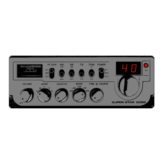
Summary of Contents for Super Star 2200
- Page 1 CHASSIS PCMA001S Superstar 2200 Alan 88S - Argus 5000 - Cobra 148GTL DX (fake)- Colt 2400 - Falcon 2000 - Ham International 8040 - HyGain 80 - Lafayette 240FM - Mongoose 2000 - Nato 2000 - Palomar 2400 - Palomar 5000 - TriStar...
- Page 2 Block Schematic Diagram...
- Page 3 PCB Layout Test Points Reading Point Adjustment Description Value Band A -80 Ch. 19.655MHz Band B -40 Ch. 19.880MHz Band C CEPT 20.105MHz Band D + 40 Ch. 20.330MHz CT12 Band E + 80 Ch. 20.555MHz Band C CEPT 20.1035MHz 0utput to RF local oscillator 37.660-38.100MHz for CEPT VCO-Coil VCO DC Voltage...
- Page 4 Adjustment Description Value RECEIVER RF Input RF Input RF Input 1. IF 10,7MHz 1. IF 10,7MHz AM IF 455kHz AM Detector 455kHz SSB IF 455kHz SSB Detector FM Discriminator TRANSMITTER PLL Output to Converter 37.660 - 38.100MHz for CEPT PLL Output to Converter 37.660 - 38.100MHz for CEPT Transmitter Output 26.965 - 27.405MHz for CEPT...
- Page 5 Modification for SuperStar 2200 To get 10-meter, cut trace from + 5 Volt to Pin 8 and 9. To get 12-meter, cut trace from GND to Pin 7 and connect Pin 7 to + 5 Volt. Make a new VCO Block.
- Page 6 Frequency List Ch. A = - 80 B = - 40 C = CEPT D = + 40 E = + 80 26.065 26.515 26.965 27.415 27.865 26.075 26.525 26.975 27.425 27.875 26.085 26.535 26.985 27.435 27.885 26.105 26.555 27.005 27.455 27.905 26.115...
- Page 7 Components AN252 and AN7140 5 Watt Audio Power Amplifier Similar to NTE1365 Pin Name Description Output GNDGround Input Ground Positive Supply Voltage AN240P FM IF Amplifier and Discriminator Similar to LA1365 KA2101 TA7176P HA1125 LM3065N ULN2165N LSC1008P GL3201 SN76664N Description: The AN240P is a versitile device in a 14-Lead DIP type package incorporating IF limiting, detection, electronic attenuation, audio amplifier, and audio driver capabilities.
- Page 8 AN612 Modulator / Demodulator / Mixer Similar to NTE1249 Name Description Signal input Bias input Signal input Ground Bias output Positive Supply Voltage Output...
- Page 9 AN103, KIA6410S, KIA7310P, SK3445, TA7310P Oscillator, Mixer and Amplifier VCO for Phase Lock Loop (PLL) Pin Name Description Oscillator Input Oscillator Output Oscillator Output - Buffered Mixer Input Ground Mixer Output Amplifier Input Positive Supply Voltage - 9 Volt Amplifier Output PLL02A MC145109 MM48141 AN6040 MN6040 SM5109 TC9100 PLL Frequency Synthesizer...
- Page 10 Down-converting of the frequency to the divider This PLL Circuit use a Mixer and a X-Tal Oscillator to convert the output frequency f to the f the PLL Circuit. The X-Tal frequency is f XTAL The output frequency can be changed by changing the mixing-xtal or add a new mixing-xtal to the oscillator.
- Page 11 1/2R A built-in divided by 2 circuit which provides an output of half the 10.240 MHz Reference Oscillator frequency, or 5.12 MHz. If used, it normally connects to a tripler circuit to provide a 15.360 MHz signal(5.12 MHz x 3) which can be used for loop mixing with the 16 MHz VCO. This mixing provides a low-frequency signal input or downmix to the Programmable Divider.
- Page 12 ..P Program Select pins from Channel Selector switch. (Sometimes called "D" for ''Data'' rather than "P" for ''Program''.) These pins control the actual channel selection. They may control selection through straight binary coding, BCD, or ROM. The sub-numbers indicate the weight or significance of each pin.
- Page 13 RX 1st Frequency "N" digital VCO freq. Ch. No. IF freq. P0 P1 P2 P3 P4 P5 P6 P7 P8 (MHz) codes (MHz) (MHz) 26.965 17.18 37.66 26.975 17.19 37.67 26.985 17.20 37.68 27.005 17.22 37.70 27.015 17.23 37.71 27.025 17.24 37.72 27.035...
- Page 14 A series of "1"s and "0"s appears in the chart for each of the 40 channels. A "1" means +DC is applied to that pin, and a "0" means that pin is grounded. The pin having the highest binary value or "significance"...
- Page 15 its two inputs, until an exact match occurs again. While this appears to be just a trial-and-error process, the whole thing happens in the time it takes you to change from Ch.1 to Ch.2 ! Receiver IF`s We've now seen how the Ch.1 PLL mixer signal of 37.660 MHZ provides the RX first IF injection. Now note from Figure that we can make even a third clever use of the 10.240 MHz Reference Oscillator.
Need help?
Do you have a question about the 2200 and is the answer not in the manual?
Questions and answers