
Related Manuals for Vertex Standard VX-537


Summary of Contents for Vertex Standard VX-537
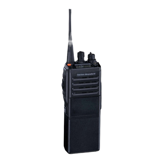
- Page 1 VX-537 Hand-Held Portable Land Mobile Transceiver perating anual Vertex Standard LMR, Inc. 4-8-8 Nakameguro, Meguro-Ku, Tokyo 153-8644, Japan...
-
Page 2: Intrinsic Safety (Is) Information
After reading it, keep the manual handy for quick reference, in case questions arise later on. We’re glad you joined the Vertex Standard team. Call on us any time, because our business is communications. Let us help you get your mes- sage across. -
Page 3: Important Notice
It must be used ONLY for (1) when there is a 1” - 2” (2.5 to 5 cm) distance from the body during transmitting, or (2) for moni- toring purposes, using the speaker only, or (3) for carrying purposes. Always use Vertex Standard authorized accessories. VX-537 Operating Manual Page 1... -
Page 4: Top Panel
Blinking: Busy Channel (or SQL off) Talk-Around Mode Channel Group Number ( “01” ~ “19” and “0” ) This Channel on “DUAL WATCH” List Group Scan Enabled This Channel on “SCAN” List (this group) 8 Character Alpha-numeric Invertible Display Page 2 VX-537 Operating Manual... -
Page 5: Controls And Connectors
PTT Switch SIDE SEL2 Key MIC/SP Jack (External MIC/SP) Battery Release Button Battery Terminals Maximum Input Voltage: 9 V DC Maximum Input Current: 2.5 A Maximum Internal Capacitance: 30.33 µF Maximum Internal Inductance: 1 µH VX-537 Operating Manual Page 3... -
Page 6: Before You Begin
Do not reverse-connect the battery terminals. Do not parallel-connect the battery terminals. Do not change batteries in hazardous locations. To reduce the risk of explosion, recharge the batteries outside of hazardous locations. Page 4 VX-537 Operating Manual... -
Page 7: Battery Charging
Do not allow any metal objects to short the terminals in the nest of the Charger Stand, as a short-circuit could cause overheating of the charger circuitry. VX-537 Operating Manual Page 5... -
Page 8: Low Battery Indication
(this “deep cycling” technique promotes better long-term battery capacity). Caution Danger of explosion if battery is replaced with an incorrect bat- tery. Replace only with the same or equivalent type. Page 6 VX-537 Operating Manual... -
Page 9: Operation
Note VX-537 Operating Manual Page 7... -
Page 10: Basic Operation
Note: Some models are programmed so that the operating chan- nels are selected by the Soft key and the memory channel group is selected by the CH selector knob. For further details, contact your Vertex Standard dealer. Page 8 VX-537 Operating Manual... - Page 11 16-key version, the [ A ] , [ B ] , [ C ] , and [ D ] function keys may be used to activate SIDE SEL1 one of these functions, if programmed by the dealer. See the next section for details regarding the available features. SIDE SEL2 VX-537 Operating Manual Page 9...
- Page 12 Do not remove/install the MH-50 Speaker/Microphone in a haz- ardous location. Note: Save the original plastic cap and its mounting screws. They should be reinstalled when not using the Speaker/Micro- phone. Page 10 VX-537 Operating Manual...
-
Page 13: Soft Key And Toggle Switch Functions
Soft Key and Toggle Switch Functions The VX-537 includes the [ TOP SEL1 ] , [ TOP SEL2 ] , [ SIDE SEL1 ] , and [ SIDE SEL2 ] Keys, and the Toggle Switch, while the 16-key ver- sion additionally provides [ A ] , [ B ] , [ C ] , [ D ] function Keys. - Page 14 Encryption Off ø 1 Follow-Me Scan Group Up Group Down Channel Up Channel Down Call / Reset ø 2 Speed Dial Emergency Monitor Lamp ACC1 ACC2 1: Requires Encryption Unit ø 2: 16-Key version only ø Page 12 VX-537 Operating Manual...
-
Page 15: Advanced Operation
Note: Your dealer may have programmed your radio to stay on one of the following channels if you press the PTT switch during scan- ning pause: Current channel (“Talk Back”) “Last Busy” channel “Priority” channel “Home” channel “Scan Start” channel VX-537 Operating Manual Page 13... -
Page 16: Dual Watch
Note that your dealer may have made provision for “Talk Around” chan- nels by programming “repeater” and “Talk Around” frequencies on two adjacent channels. If so, the key may be used for one of the other Pre- Programmed Functions. Page 14 VX-537 Operating Manual... - Page 17 Lock Switch the Toggle switch to lock the top-panel keys; this can be en- abled to prevent radio settings from being disturbed. VX-537 Operating Manual Page 15...
-
Page 18: Follow-Me Scan
The radio will then scan back and forth between the original User-assigned Priority Channel and the newly-selected channel. The Priority Channel you have assigned (before pressing the key) will be retained in memory until you change it. Page 16 VX-537 Operating Manual... -
Page 19: Channel Group Selection
Soft key. To restore a particular channel to your scanning list, press and hold in the Soft key again for one second; “-STOP-” will appear on the LCD for one second after pressing the Soft key. VX-537 Operating Manual Page 17... -
Page 20: Speed Dial
The VX-530 includes an “Emergency” feature which may be useful if you have someone monitoring on the same frequency as your transceiv- er’s channel. For further details contact your Vertex Standard dealer. Monitor Press the assigned Soft key to override both Tone and DCS Squelch. -
Page 21: Dtmf Paging System
When your radio is paged by a station bearing a tone sequence which matches yours, your radio’s squelch will open and the alert ringer will sound (unless you have disabled it). The three-digit code of the station which paged you will be displayed on your radio’s LCD. VX-537 Operating Manual Page 19... -
Page 22: Accessories And Options
Swivel Belt Adaptor (Requires LCS-2) SBC-1 LCS-2 Swivel Belt Attachment Antenna Jack Adaptor (Stud to BNC) CN-7 The following optional units are not available for intrinsically safe use, because they do not have an IS rating. If any of the optional units listed below is used with the VX-537, the radio is no longer intrinsically safe, and must not be used in hazardous locations. Battery Packs: FNB-29A and FNB-29AL Alkaline Battery Tray: FBA-19 5-Tone Sequential Decoder Unit: F5D-14 Page 20 VX-537 Operating Manual... - Page 23 Part 15.21: Changes or modifications to this device not expressly approved by Vertex Standard could void the user’s authorization to operate this device.
- Page 24 Copyright 2012 Printed in Japan Vertex Standard LMR, Inc. All rights reserved. 1211B-0Y No portion of this manual may be reproduced without the permission of Vertex Standard LMR, Inc.
Need help?
Do you have a question about the VX-537 and is the answer not in the manual?
Questions and answers