Table of Contents
Advertisement
Quick Links
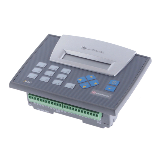
JZ10-11-T17
Before using this product, the user must read and understand this document.
For additional information regarding this product, refer to the user guide and technical specifications.
All examples and diagrams are intended to aid understanding, and do not guarantee operation.
Unitronics accepts no responsibility for actual use of this product based on these examples.
Please dispose of this product according to local and national standards and regulations.
Only qualified service personnel should open this device or carry out repairs.
Failure to comply with appropriate safety guidelines can cause severe injury or property damage.
Do not attempt to use this device with parameters that exceed permissible levels.
To avoid damaging the system, do not connect/disconnect the device when power is on.
Environmental Considerations
Do not install in areas with: excessive or conductive dust, corrosive or flammable gas,
moisture or rain, excessive heat, regular impact shocks or excessive vibration.
Ventilation: 10mm space required between the controller's top/bottom edges & enclosure walls.
Do not place in water or let water leak onto the unit.
Do not allow debris to fall inside the unit during installation.
Mounting
Dimensions
147.5 mm (5.807")
Add-on modules
Note: Installing an add-on module requires space.
During installation
72 mm (2.835")
Unitronics
Jazz™ Micro-OPLC™ Installation Guide
6 Digital, 2 Analog/Digital, 2 Analog Inputs, 7 Transistor
Outputs
12 mm (0.472")
46.6 mm (1.835")
After installation
27.5 mm
(1.083")
113.7 mm (4.476")
13.2 mm (0.52")
Panel mounting
- Cut-out:
117 x 89mm (WxH) 4.606"x 3.504"
- Hold bracket against unit while
tightening screw
Panel
5mm (max)
0.197" (max)
Bracket
Gasket
16.8 mm (0.661")
1
Advertisement
Table of Contents

Summary of Contents for Unitronics Jazz Micro-OPLC JZ10-11-T17
- Page 1 All examples and diagrams are intended to aid understanding, and do not guarantee operation. Unitronics accepts no responsibility for actual use of this product based on these examples. Please dispose of this product according to local and national standards and regulations.
- Page 2 In addition, 1 input may be wired as a pnp input, while the other is wired as an analog input. Note that if 1 input is wired as an npn input, the other may not be wired as an analog input. AN0 and AN1 are analog (current) inputs that may be wired using 2, 3, or 4 wires. Unitronics...
- Page 3 Input wiring I0-I5 pnp (source), I6 -I7 npn (sink) 24VDC I7 I6 I5 I4 I3 I2 I1 I0 +V 0V I6-7 I0-5 24VDC Digital Outputs, Outputs’ Power Supply Output wiring 24VDC 00 01 02 03 04 05 06 24VDC Unitronics...
- Page 4 24VDC The information in this document reflects products at the date of printing. Unitronics reserves the right, subject to all applicable laws, at any time, at its sole discretion, and without notice, to discontinue or change the features, designs, materials and other specifications of its products, and to either permanently or temporarily withdraw any of the forgoing from the market.
Need help?
Do you have a question about the Jazz Micro-OPLC JZ10-11-T17 and is the answer not in the manual?
Questions and answers