Table of Contents
Advertisement
Wireless IP Camera
Version 1.00
(English)
BEFORE GETTING STARTED
This UM is designed to aid you to get started with the device. If you experience problems following these guides or need further
information pertaining to the device, please visit our website at www.prolink2u.com. All specifications are subject to the
manufacturer's configuration at the time of shipping and mau change without prior notice, written or otherwise.
Advertisement
Table of Contents

Related Manuals for PROLiNK PIC1007WP


Summary of Contents for PROLiNK PIC1007WP
- Page 1 Wireless IP Camera Version 1.00 (English) BEFORE GETTING STARTED This UM is designed to aid you to get started with the device. If you experience problems following these guides or need further information pertaining to the device, please visit our website at www.prolink2u.com. All specifications are subject to the manufacturer’s configuration at the time of shipping and mau change without prior notice, written or otherwise.
-
Page 3: Table Of Contents
Table of Contents Table of Contents ........................1. Introduction ......................... 1.1.The Differences ........................2. Installation & Setup ......................1.2.Hardware Overview ......................1.3.Quick Installation and Usage ....................1.3.1.Step 1 : Connect the IP CAM to the home/office network ..........1.3.2.Step 2 : Install the LiveView Software on the notebook/PC . - Page 4 Register Online For Your Product Warranty @ www.prolink2u.com/register ........ PROLiNK® is a trademark of FIDA INTERNATIONAL (S) PTE LTD and is manufactured under its authority. All other brands, products, services, logos and company names mentioned herein are trademarks of their respective owners. All specifications, designs and contents are subject to changes without prior notice.
-
Page 5: Introduction
1. Introduction The PROLiNK® PIC1007WP MegaPixel Dual Lens Wireless IP Camera (will be referred to as “IP Camera for the entire document) is designed with the ” user friendly“ idea in mind. You can install the IP Camera easily on your home network and then access the IP Camera anywhere in the world from your mobile or pc with only a camera id and password. -
Page 6: Installation & Setup
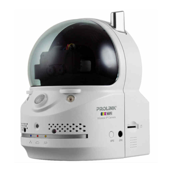
2. Installation & Setup l a t , t s s ’ t products. 1.2. Hardware Overview Figure 2-1: IP Camera Hardware Overview Dual Lens External Speaker Jack Power Jack IR LED Micro-SD Card Slot Bracket Screw Jack Internal Speaker Reset Button Microphone WPS Button... -
Page 7: Quick Installation And Usage
IP Camera should be connected to the Internet immediately. The Internet status LED should be red and constant to indicate it has a good connection status. If the LED is blinking, please refer to section 1.7~1.9 to try other network settings. (Wired) PIC1007WP NAT/Router Internet Power Adapter Ethernet Cable Figure 2-2: Connect Ethernet cable to a switch/router. -
Page 8: Step 3 : Use Liveview Program To See The Video
1.3.3. Step 3 : Key Password in LiveView and Ready to View If the computer and IP Camera are connected to the same network, the IP Camera ID will automatically be displayed in the “Auto Search” list . To see the video, just double click the IP Camera ID item in the “Auto Search”... -
Page 9: Wireless Connection
IP Camera. The IP Camera will detect the Ethernet cable unplugged condition and start the WiFi connection. After the WiFi is connected, the IP Camera will connect to the Internet immediately. PIC1007WP NAT/Router Figure 2-7: Unplug the Ethernet cable if WiFi test is successful. -
Page 10: Web Configurations
3. Web Configurations You can login to the web configuration page by directly key-in the IP address of the IP Camera or right-click the searched IP Camera in the “Auto Search” list of the LiveView Software and click the “Web Configure” to open the login window of the IP Camera. -
Page 11: Information
1.5. Information The default page of the web configuration of the IP Camera is the Information page. You can see the model name/firmware version, IP Camera ID, registration status, network type and current video settings (bandwidth, resolution), in this page. The IP Camera can only be viewed remotely by the LiveView Software when the IP Camera is connected. -
Page 12: Video Display
1.6. Video Display This display page allows you to view the video display and control the pan/tilt movement of the IP Camera. For the first time use of this display on a computer, an ActiveX component will be automatically downloaded into the browser. -
Page 13: Network
1.7. Network The Network page allows you to modify the Wired Networking, WiFi Security and Advance Network settings. The default settings use DHCP to obtain an IP address automatically. In most of the home and office network environment, there is a DHCP server running. In this situation, by using these default settings, the IP Camera can work immediately most of the time. -
Page 14: Wifi Security
1.8. WiFi Security You can connect the IP Camera to the network via wireless. If your network environment has an 802.11 b/g/n router or AP running, you can check the “Enable WiFi function” button to use the wireless. Figure 3-7: WiFi security disabled page In order to use the wireless network, you need to fill the following fields: SSID –... - Page 15 Figure 3-8: WiFi security enabled page 1. Click the “WiFi test” button to check if the IP Camera can connect to the wireless network for these settings. You will need to unplug the Ethernet cable to enable the wireless connection after the “WiFi test” is successful.
-
Page 16: Advanced Network
1.9. Advanced Network In some special situation, your network environment only provides PPPoE connection (ADSL service); there is no NAT/router available. You will then need to set the PPPoE settings in the “Advanced Network” page. Only the PPPoE username and password are needed to let PPPoE work. After the “Save & Apply” button is pressed, the PPPoE function will work immediately. - Page 17 5. Frame rate – the video frame display rate. Higher value means faster movement and continuity in the video display. 6. Favor/Preference – Video Motion/Image Quality/Better Quality/Best Quality. When the real bandwidth is not enough for the selected “Internet speed”, the system will need to degrade the video motion or image quality.
-
Page 18: Mobile Video Settings
1.11. Mobile Video Settings The IP Camera can be viewed from a 3G mobile phone, please download “mLiveview”/”mLiveviewHD” software from App Store for iPhone/iPad and “mLiveview” from Android Market for Android Mobiles and Tablets. The video frame rate, resolution and bandwidth for 3G mobile access could be set independently from the normal video view. -
Page 19: Email/Ftp Alarm
1.13. Email/Ftp Alarm The IP Camera provides the Email function that will send out an email with a jpeg picture attached when there is an event trigger. Alternatively, it can also send captured jpeg picture to a ftp server. You can enable or schedule the Email/ftp function in this page 1. - Page 20 For the email message to work, a SMTP server is required. Click the “advanced” button will display the SMTP server settings page. A default SMTP server is provided, however so you could also specify your own SMTP 1. SMTP server – this is the IP address and port of the SMTP server that will provide the send email service. This server is irrelevant to the “Email recipient”...
-
Page 21: Speaker Alarm Settings
1.14. Speaker Alarm Settings The IP Camera provides Speaker Alarm function that act like a conventional alarm siren. Any PIR or motion detection could trigger the speaker alarm. 1 1. Speaker alarm trigger– select the trigger mode of the speaker alarm a. - Page 22 5. The “NAS access account” and “NAS access password” are the username and password to login into the specified “Shared folder name” of the NAS device. 6. NAS Scan – use this to scan for some specific NAS devices in the same network. Not all the NAS devices are supported for this scan function.
-
Page 23: Sd-Card Settings
1.16. SD-Card Settings The IP Camera provides recording of video files into a standard Micro SD-Card. Since this recording is directly to the SD-Card, there is no network packets loss problem when recording to remote device through internet. Notice When the IP Camera is doing SD-Card recording, this is counted as one video user. Please refer to appendix B for maximum simultaneous users. -
Page 24: Infrared Thermometer
1.17. Infrared thermometer There is a built-in Infrared Thermometer on the camera, it will display the current temperature of the surveillance area on the video display screen. You can set a specific temperature range for the thermometer to trigger in schedule event. When the temperature is out of range, it can trigger alerts like email/ftp, speaker alarm or start recording to NAS and SD card Figure 3-18: Infrared Thermometer settings page... -
Page 25: Scheduling
1.18. Scheduling The IP Camera provides scheduling function that triggers event actions such as E mail/Ftp sending NAS Micro-SD recording or speaker alarm. Total of 12 schedules can be added with combination of event actions. Before any schedule can be added, the “Schedule” option must enabled in the event actions settings. . There is no conflict check for the scheduling, it means that the scheduling time could be overlapped, and the IP Camera will do all the scheduled events during the overlapped time period. -
Page 26: Led Control
1.19. LED Control The IP Camera provides the Led Display Control function, you can enable or disable the led display/indication on the front panel of the IP Camera device. The related settings are explained below: 1. Normal led display – select this to display all the LED Indicators on front panel. 2. -
Page 27: Admin
1.21. Admin In this page, you can edit the web login account. This account allows you to login to the IP Camera settings and make changes to it. The default username is “admin” and password is empty. If the login account is forgotten, you can easily reset the IP Camera to the factory default settings by following the steps in section 1.25 and login with the “admin”... -
Page 28: Upgrade
1.22. Upgrade If there is new firmware available for this IP Camera, you can upgrade the firmware from this page. Please ask for the correct information about FTP server, username/password account and firmware filename from your supplier, and then do this upgrade. When you start the upgrade process, the page will show the upgrade status. During the upgrade proce , do not power off the IP Camera, otherwise the IP Camera will enter into the safe mode (section 1.24). -
Page 29: Reboot
1.23. Reboot You can restart the IP Camera manually in this page. All the connected video viewing users will be disconected. Figure 3-24: System reboot settings page Figure 3-25: System reboot under-going page EN 29... -
Page 30: Safe Mode
1.24. Safe Mode If by some abnormal operation, for example, power off during the upgrade procedure, the IP Camera will enter into safe mode. You will see the following “Safe mode” page when login to this IP Camera. Please do the upgrade operation immediately to recover the system. -
Page 31: Features & Specifications
4. Features & Specifications Features 1.26. True Plug & Play. Only ID/Password is required. No IP address or DDNS settings. H.264 latest video compression technology. Megapixel resolution of up to 1280x800 pixels at 30 fps. Unique Dual Lens and Dual Sensor for day/night operation. Pan/Tilt Control. - Page 32 Lens 4.2 mm, F2.4, viewing angle: 66°, fixed iris. focus range: 30 cm to infinity Day & Night separate lens Buttons One reset button to factory default settings One WPS button for automatic WiFi setup Indicators One LED for Internet connection status indication One LED for Ethernet connection indication One LED for SD card recording indication Video compression...
-
Page 33: Package Contents
5. Package Contents IP Camera Quick Installation Guide MODEL NO: PIC1007WP Quick Installation Guide Wireless-N IP Camera with Pan/Tilt Version 1.00 (English / Indonesian) BEFORE GETTING STARTED This document is designed to aid you to get started with the device. If you experience problems following these guides or need further information pertaining to the device, please visit our website at www.prolink2u.com. -
Page 34: Appendix A. List Of Tested Nat/Router Device
IP Camera video . In this situation, please contact your MIS person to solve the problem. Brand Name Model Name WNR1004, WNR1008, WNR1009, WN1010, PROLiNK WNR1011, H5001N, H5004N, PWH2004 Asus WL 550gE Belkin... -
Page 35: Appendix B. Performance Information
Appendix B. Performance Information Video Performance Information The video quality is dependent on the video parameter settings and the network quality. If you want to have a better video quality, you will usually set higher resolution and higher frame rate. This is fine when you are viewing the video locally in the same network. -
Page 36: Appendix C. Troubleshooting
Appendix C. Troubleshooting 1. Wh y is the LED indicators on the camera keep on flashing in sequence? This is due to t he IP Camera being dis connected from the Internet . Please ensure your Ethernet or Wifi connection are setup properly and check if you have an Internet connection. - Page 37 Please download Mac version of Liveview from our website. The Mac version is a beta version which means it is still work in progress therefore some functions may not work or being disabled. The focus of the IP Camera is pre-adjusted and fixed during production so you are not required to adjust it. Focus range is from 30cm to infinity.
- Page 38 14. How do I i ° Go to the web configuration page of the camera > Login Credential > Video > Video Flip > Select Video Flip > Save & Apply I can see the video from remote location, but the video quality is not good and sometimes the video will .
- Page 39 20. How to view or playback the recorded clips? Execute LivePlay from Start > All Programs > PROLiNK > IP Camera > LivePlay Click Open Record, the record data windows will be prompted and all recorded clips are listed on the Recorded Files section follow by date (YYYYMMDD) of the recording sessions.
- Page 40 Note: a) All recorded video clips on the same day will be combined into one video clip playable by the LivePlay player. b) User can playback the recorded video clips through third-party video player, eg: VLC Player (visit official website http://www.videolan.org/vlc), and: Open the video clips saved folder.
- Page 41 LiveView settings to “High” or “Very high”. This will tremendously improve the video quality in dark environment. PIC1007WP comes with built-in IR LED and greatly improves the video clarity even in total darkness. However when IR LED is turned on in the dark room, the video will be displayed in black and white only.
- Page 42 26. Can I connect the IP Camera directly to my PC/notebook with an Ethernet cable? Yes. If the IP Camera is directly connected to your PC/notebook computer using an Ethernet cable, the IP Camera will automatically use an IP address called “auto IP” with IP address 169.254.xxx.xxx. Run the LiveView Software to access the IP Camera, the Camera ID should be displayed on the “auto-search”...
-
Page 43: Worldwide Customer Care Centers
Register Online For Your Product Warranty @ www.prolink2u.com/register PROLiNK® is a trademark of FIDA INTERNATIONAL (S) PTE LTD and is manufactured under its authority. All other brands, products, services, logos and company names mentioned herein are trademarks of their respective owners. All specifications, designs and...
Need help?
Do you have a question about the PIC1007WP and is the answer not in the manual?
Questions and answers