Table of Contents
Advertisement
Advertisement
Table of Contents

Related Manuals for XTS 9200 Series

Summary of Contents for XTS 9200 Series
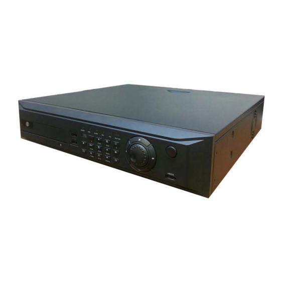
- Page 1 XTS- 9200 Series User’s Manual Intelligent Security Solutions www.xtscorp.com...
-
Page 2: Preface
Preface Sincerely thank you for selecting our product. We will offer the best service for you wholeheartedly. We take 16 channel DVR9200 Series (960H) as a sample. Different models will have a little difference and it will work between product function and operation. It’s for reference only. -
Page 3: Table Of Contents
CONTENT Preface ........................................ 1 Chapter 1 Brief Introduction about the DVR............................6 1.1 Summarization ..................................6 Chapter 2 Technology Guideline and Main Functions........................... 7 2.1 Technology Guideline ................................7 2.2 Main Functions ..................................8 Chapter 3 Equipment Installation and Illustration ..........................12 3.1 Installation Environment and Cautions .......................... - Page 4 3.4 Mouse Operations .................................. 20 3.5 Menu Operation Description..............................22 3.5.1 Menu Structure Chart ..............................22 3.5.2 Menu Option Schedule ..............................23 Chapter 4 Device Operation ................................26 4.1 Power On/Off and Login/Lock .............................. 26 4.1.1 Keystroke Unlock/Lock ..............................26 4.1.2 System Login................................
- Page 5 4.4.6 COM Settings ................................52 4.4.7 PTZ Settings................................. 52 4.4.8 Network Settings ................................54 4.5 Manual Record ..................................61 4.6 Manual Alarm..................................62 4.7 HDD Management ................................63 4.8 Information Inquiry ................................64 4.8.1 System Information............................... 64 4.8.2 Record Status................................64 4.8.3 Alarm Status.................................
- Page 6 Appendix 1 IE Browse Operation Instructions ............................. 76 1.LAN Configuration for IE Browse ............................... 76 2. WAN Operation Instructions ..............................77 Appendix 2: Net DVR Q&A ................................. 82...
-
Page 7: Chapter 1 Brief Introduction About The Dvr
Chapter 1 Brief Introduction about the DVR 1.1 Summarization This DVR is designed for video/audio digital surveillance system. They adopt H.264 compress format, integrate embedded RTOS and processor to realize all of the functions like video and audio acquisition and compression, storing, remote control, Multi-PTZ control and alarm in a single board. -
Page 8: Chapter 2 Technology Guideline And Main Functions
Chapter 2 Technology Guideline and Main Functions 2.1 Technology Guideline 1. Video Parameters Video input: composite video input PAL (25fps) NTFS (30fps) (BNC, 1Vp-p, 75Ω) Video output: 1 channel composite video output (BNC, 1Vp-p, 75Ω) PAL (625line/frame) NTSC (525line/frame) 2. Audio Parameters Audio input: BNC interface, input resistance: 10KΩ, input extent: Vp-p=2.0V LINE Audio output: BNC interface, input resistance: 10KΩ, input extent: Vp-p=2.0V LINE Voice intercom: input (3.5MM interface, input resistance: 10KΩ, input extent:Vp-p=2.0V LINE in/50mV MIC in)... -
Page 9: Main Functions
12. Network Interface: 10M/100M/1000M self-adaption Ethernet interface 13. Power Consumption: ≤66W (71W Full load HDD) 14. Power Supply: 220±30%V, 50±3%HZ, 110±20%V, 60±3%HZ optional 2.2 Main Functions High effective RTOS and embedded processor are adopted in this series DVR, as well as all functions needed for the monitoring system are integrated. - Page 10 Recording Function 1. Supporting 4 recording modes: manual, schedule, motion and alarm recording. 2. Video motion detection function: 5 sensitive levels available. 3. Supporting screen shield. Up to 4 mask areas can be set in each channel, which supports real-time mask, recording mask and full screen mask.
- Page 11 4. Supporting video parameter adjustment to every single channel. (Brightness, contrast, saturation, chroma, vertical position) 5. Supporting channel auto sequence function. 6. Supporting intercommunication function. Storing and Backup Function 1. Providing specialized USB2.0 backup interface in the back panel. 2. Backup record files through client manager software. 3.
- Page 12 2. Perfect network side control order (Client manager and IE browser can be used to operate DVR) 3. Supporting Web Server function (available to access the host via IE browser) 4. User can control PTZ, lens, wiper and so on via internet. 5.
-
Page 13: Chapter 3 Equipment Installation And Illustration
Chapter 3 Equipment Installation and Illustration 3.1 Installation Environment and Cautions Installation Environment º º º º Normal working temperature is -10 C ~45 C ; storage temperature is -10 C ~70 Normal working humidity is 15%~85%RH The equipment must keep horizontal both in installation and in using ... - Page 14 Cautions : Keep wet hands or wet materials away from power switch or DVR Make sure machine and case are grounded to avoid signal interference and static damage(earth interface is on the back panel of machine) Keep voltage stable to avoid abnormal power cutoff. Don't turn off machine by disconnecting the master switch ...
-
Page 15: Attentions On Installing Hard Disk
3.1.1 Attentions on Installing Hard Disk 1. High speed hard disks (above 7200 rpm) are recommended 2. The capacity of the single hard disk is above 32GB at least, each HDD supports maximum 2T (Note: 3T HDD is only supported by new file system) 3. -
Page 16: Device Interface
3.3 Device Interface 3.3.1 Video/Audio Connection Video output: 1 VGA output, 1CVBS output, 1 HDMI output Audio output cautions: Please use 3.5mm two-port lotus line if you want to connect speakers. 3.3.2 USB Backup Interface The form of backup USB disk is FAT32. Please enter "Disk Management" if you want to format (Refer to "Disk Management"... -
Page 17: Alarm Input/Output Connection
3.3.4 Alarm Input/Output Connection Alarm input: input resistance impedance 22KΩ, voltage comparison (0V-0.8V) (Instruction: When the voltage between GND and output is in the interval of 0V-0.8V, the machine won't alarm; When the voltage is above 0.8V, the machine will alarm) Alarm output: relay (120VAC/1A, 24VDC/1A), Normal (relay open), Alarm (relay closed) Sensor power: the machine provides a +12V DC power output port. - Page 18 power supply NO/NC +12V Sensor Input 1 The DVR can not recognize the triggered if the sensor is parallel connected. +12V Input1 C NO/NC C NO/NC C NO/NC Sensor Sensor Sensor...
-
Page 19: Rs-485 Connection
2. Alarm output connection: Normally, the alarm output side is off and without voltage output . So the alarm equipments need separated power supply to work. Power Output 1A Output 1B Alarm Normally, alarm power is very high. Instead of DVR power supply, separated power supply is recommended. The power limit of the external alarm is 120V/AC, 24V/DC 1A. -
Page 20: Keyboard Controlling
RS485: For controlling PTZ, series keyboard and transparency port connection. 3.3.6 Keyboard Controlling Series keyboard is used to control single or multiple DVR (Controlling models with the same channels by keyboard is commended). The function of keyboard is consistent with DVR panel (Note: the keyboard is only available after adding our Protocol and passing our test) take connecting keyboard to RS485 interface for example: 1. -
Page 21: Mouse Operations
3.4 Mouse Operations Besides remote control and operation menu of the front panel, mouse can also be used to control the DVR. Right-click: 1. Right-click in the login system to enter the interface as right 2. Right-click to pop up login menu when the DVR is in the locking and monitoring status Default user name is "admin", default password is "888888"... - Page 22 3. Double left click to eliminate channel video mask and motion detection mask 4. Double left click to change the position of PTZ controlling position Soft keyboard interface as below:...
-
Page 23: Menu Operation Description
3.5 Menu Operation Description 3.5.1 Menu Structure Chart Main Menu... -
Page 24: Menu Option Schedule
3.5.2 Menu Option Schedule Menu Instruction Time Query Search record data by time and display graphical data record and playback Data Event Inquiry Search record data and playback by record event type Query Backup (Manual, time) backup, search and playback record data Manageme 1.Host name, remote control locking enabled, host address code 2.Record coverage type (auto, manual) - Page 25 DDNS Select DNS, set user name and password for domain name resolution PPPOE Set dial-up user name and password to dial System Network Email Set server, email user name, password, email address, port number, cycle, Setup Setup Setup snapshot uploading, SSL secure login Platform Set monitoring port Server...
- Page 26 Logout Logout Shutdown Shutdown Shutdown (If you want start up the device, please click startup button on the front panel) Restart Restart device locally Single Picture Switch Quickly switch single picture Multiple Picture Switch Quickly switch the picture form Quickly enter to inquire the record data (time query, event query), record data graphical Data Inquiry display and playback PTZ Controlling...
-
Page 27: Chapter 4 Device Operation
Chapter 4 Device Operation 4.1 Power On/Off and Login/Lock Power on: After connecting the power cable, the front panel of the DVR will start and standby. Click "power" of the remote control for 3 seconds to enter the running status. Power off: When the system is under the running state, click "power"... -
Page 28: System Login
4.1.2 System Login When the system is in the locking status " ", press "login/lock" of the remote control, click lock icon " " or right click to pop up login interface as below: input user name and password (distributed by authority in advance). After you input correct password and press "enter"... -
Page 29: System Lock
4.1.3 System Lock When the system is in login status, left click "Main Menu" "System Settings" "General Settings" to enter the interface, set automatic locking function and time (default is 3 minutes) in combo box of the right side. If no operation is done during the time you set, the system wills automatically logout. - Page 30 3) Alarm status icon: click " " to enter "alarm status" to check alarm info or eliminate alarm sound 4) Audio icon: click " " to enable or shutoff audio 5) Channel preview order adjust icon: Single click to adjust the order of preview channels 6) Display/hide status bar: click "Hide status bar"...
-
Page 31: Data Inquiry And Playback
4. Network setting, you can set the IP, gateway, DNS, command port, HTTP port; Click “Save” after set finish and choose “Next”. 5. HDD management, choose the HDD number which you want format then click “Format” , after pop-up “Are you sure to format HDD?”... - Page 32 Selected inquiry channel is the playback channel. Click graphical interface (the position of white vertical line is the start time of record) or input start time of record playback, then click "Play" or double click graphical interface to play the record. ...
- Page 33 Selected inquiry channel is the playback channel. Select record mode in the mode combo box. Select record data with remote control cursor and put into "Play" to play the record, or double click with mouse. Click "Page Up", "Page Down" to turn the pages. ...
- Page 34 1. Play the record data. 2. Choose the needed recording data. A, Click the clip icon to choose the start time, as below picture: B, Click the clip icon again to choose the end time 3. Auto pop-up clip and backup window, as the below left picture: 4.
- Page 35 Picture playback interface function, as below picture: 1. Support single channel or multi channel picture playback. 2. Support Split-screen format playback: When playback single channel picture, click the split-screen format icon in player can shift to 1/4/8 and do multi picture playback. 3.
-
Page 37: Backup Management
4.3 Backup Management There are 2 ways for the system to backup: (1) Backup to remote PC via network (refer to client instruction) (2) USB flash disk backup, supporting hot plug, the format of backup disk must be FAT32. "Main Menu" "Backup Management" to enter the interface as below: 4.3.1 Manual Backup 1. - Page 38 2) Select "Capacity inquiry" to check the capacity of backup data. 3) Select "Manual" to pop up the confirmation page, confirm it again and the system will execute backup automatically. 4) It's able to backup if there is record. No need to wait. 2.
-
Page 39: Schedule Backup
Note: Progress bar is not able to be dragged when playing. 4.3.2 Schedule Backup Click "Schedule" in Backup Management interface to enter schedule backup interface as right: Settings include: enable schedule backup function, selecting schedule backup channel, record mode, backup time, and backup device. - Page 40 DVR, host ID is used to identify device, also it's used to lock/unlock remote control. Record overwrites type: "Auto" is recommended. After HDD is full, the system will overwrite earliest file. The overwrite is by file, so when the overwrite begins, the HDD capacity will be 0. If you select "Manual” type, the system will prompt whether to overwrite the earliest file and won't record anymore.
-
Page 41: Output Settings
port123, default time zone is GMT+08:00. 1.Time Server: default server is able to proofread time successfully; generally the default doesn't need to change. If the default time is incorrect, you can manually edit time server 2.Port: This SNTP supports TCP protocol only 3.Time Zone: Supporting 26 time zones for setting 4.Update Delay is hour, day, week and the effective range are all (1-60). - Page 42 1 Channel Settings Select "Output Settings" "Channel Settings" to enter the interface as right above: Channel settings mainly edit channel name, video mask, video parameters modifying, and video input modifying and channel position settings. (1) Channel Name Maximum 31 characters can be set in each channel's name ...
- Page 43 In some monitoring places, video mask is needed to shield some private or sensitive areas, such as password keyboard of the bank. Video Mask Types: Disabled, real time mask, record mask, full mask. Record mask and full mask supports 4 mask areas.
- Page 44 mouse to enter “video adjustment” to adjust the video parameters, the interface is as the right figure: Default video parameter: brightness (128), contrast (128), saturation (128), hue (128). Channel No.: used to switch channels, user can also setup all channels directly. ...
-
Page 45: Record Parameters
3 Sequence Settings At “Output Settings”, select “Sequence Settings” to enter the interface as the right figure above. This function is used to cruise different channels, user can select sequence channel No., sequence division, sequence interval time. Sequence format: 1ch, 4ch, 9ch, 16ch divisions. ... - Page 46 capacity, etc. After login, select “record setup” “record parameter “to enter the interface as follows figure: Channel No.: Customer can select the channel by pressing “+”, “-” on remote controller or by the mouse. Record mode: The record parameters will be active in the selected record mode. ...
-
Page 47: Schedule Record
there are (unit: bps):100K,128K,256K,512K,1M, 1.5M, 2M, 3M, 4M(Note: under the CIF maximizing the 1M., the more intense of the movement, the higher bite rate you should set). Audio: The on/off switch for audio (Tick off indicates open, otherwise means off). ... -
Page 48: Alarm Settings
4.4.5 Alarm Settings Alarm Settings is containing submenu: Motion Detection, Sensor Detection, Alarm Output, other alarm, interface is as the left figure below: 1. Motion Detection After login, click “Alarm Settings” “Motion Detection”, the interface is as the right figure above: By analyzing the real-time video, the system could confirm whether the video scene has changed or not. - Page 49 【Step 2】Choose the motion record channel. 【Step 3】Define the detecting sensitivity level: at “Motion Detection” menu select “ Sensitivity” setting, The sensitivity of the motion detection is adjustable and contains 5 levels from 1 (Lowest) to 5 (Highest). When the motion detection of the current channel happens, the system will alarm and record.
- Page 50 Alarm output: Alarm output in blue color indicates that alarm output will be processed when there is alarm occurred; if in grey color, indicates no alarm output when alarm occurred. Linkage E-mail:Select “Linkage E-mail “option (by symbol tick“√”)means the alarm relevant information will be ...
- Page 51 linkage record channels which is convenient to inquire the record data by channels. Channel buttons in blue color indicates linkage record; if in grey color, indicates no linkage record. Alarm output: Alarm output in blue color indicates that alarm output will be processed when there is alarm ...
- Page 52 After login, through “Alarm Settings” “Alarm Output” continuous operations to enter Alarm Output interface. The interface is as the right figure above: The Alarm Output interface contains below selections: Alarm Output time, Audio, Buzzer, Full Screen, Alarm Output Deployment time. ...
-
Page 53: Com Settings
4.4.6 COM Settings After login, click “System Settings” “COM Settings” to enter the interface is as the right figure: You can do the operation of connecting other serial device to DVR in this interface. DVR provide two pairs of serial connection terminal: RS485 and RX. - Page 54 Set COM type, COM device and baud rate in the “COM Settings” interface. Enter the “PTZ Settings” interface to set protocol and address code (The default PTZ address code is coincide with every channel, for instance, the first channel’s PTZ address code is 1.
-
Page 55: Network Settings
parameters of multi-preset point sequence. (Note: Only enable when system log off) (1) Sequence interval time: 0-99s. (2) Preset No.: each channel can max set 16 preset positions. (3) Range of preset No.:001-255,255 means closed. 4.4.8 Network Settings After login, user can through “Main menu” “System Settings” “Network Settings” to enter the network setup interface as the left figure below: 1. - Page 56 address column. Disable DHCP: If there is no DHCP service in the LAN, you can choose this option to designate the static IP address. When there is no auto designate IP address service in LAN, the system can edit the IP which is to designate a static IP address for the system itself.
- Page 57 After log in, through “Network settings” “Sub-stream” to enter the setting interface as the right figure: Channel No.: Customer can select the channel by pressing “+”, “-” on remote controller or by the mouse. Record mode: The record parameters will be active in the selected record mode and use the corresponding ...
- Page 58 router mapping WAN IP address. This function supports the domain name which is registered from www.oray.cn, www.dyndns.com. You can choose one of them according to the need. Oray domain name:Register on www.oray.cn and fill the correct information to apply the Oray domain name, ...
- Page 59 It shows the network information of the public network (such as IP, Subnet address) after the connection succeeds. Press “save” button, it will save the options include auto re-dial and save password. Note: You must connect the net manually after first set the “auto re-dial”. 5.
- Page 60 every interval time, and also can be uploaded a snapshot which is .jpg in default. (8) Select to upload snapshot images, the images is captured once there is alarm and sent to the Receiver email. (Note: Video lost alarm won’t upload the snapshot images.) (9)...
- Page 61 view interface. a. Set compound channel , select “Enable” button , click “Parameter setting” button to enter into the interface as below picture : b. Compound channel parameter setting please refer to “4.5.1 Record Parameters setting” Operation method as follows: 1.
-
Page 62: Manual Record
4.5 Manual Record After login to the main menu, left click the “Manual Record” pop-up the interface as the right figure: The turn on channels are in blue color, when turn off it is in gray color. Once the manual recording is started, it will not stop recording until ... -
Page 63: Manual Alarm
【1】Use remote controller “Record “button to quickly enter the setting interface, then confirm or select by mouse and confirm. 【2】After log in to the main menu interface, select the manual record for settings. 4.6 Manual Alarm After log in, through “Main Menu” “Manual Alarm” to the interface as the left figure below: This function is mainly used to manually trigger the alarm to inform related person when there occurs some kind of abnormal emergency event. -
Page 64: Hdd Management
4.7 HDD Management After login, enter the interface through “Main Menu” “HDD Management”, the interface is as the right figure above: The 1st line displays the connective HDD NO. The 2nd line displays the HDD status. The 3rd, 4th and 5th lines display the HDD capacity, free space and partition type information. -
Page 65: Information Inquiry
4.8 Information Inquiry Through “Main Menu” “Information Inquiry” to check the software version information, log information inquiry, etc, the submenu including: System Information, Record Status, Alarm Status, Online Status, and Log Inquiry. 4.8.1 System Information It displays software version, IP address etc. The interface is as figure below: 4.8.2 Record Status The interface is as the left figure below: Quick inquire the current system record status. -
Page 66: Alarm Status
4.8.3 Alarm Status The interface is as the right figure above: It shows the alarm type of each channel: Sensor alarm (Red color), motion alarm (Yellow color) and video lost alarm (Blue color). You can clear the alarm through the “CLEAR” button on the remote controller or on the front panel. You can also click by mouse the alarm status indicating light on the status bar to enter alarm status interface, select the “alarm clear”... -
Page 67: Log Inquiry
4.8.5 Log Inquiry The interface is as the right figure below: At the bottom of log information interface will display page No., user can click page up/down to check (The number of the log item is no limited). The log file can’t be recognized on PC, the log information of host side can search and show through client software. -
Page 68: Quick Settings
4.9.1 Quick Settings The interface is as below figure,firstly enter the time settings interface, continuously click by mouse the “Next” button for fast moving to “Time Setting”, “Network Setting”, “Hard disk Management”, “Record Parameter”, “Manual Record” ,etc, settings. Note: after finishing the parameter setting, click “Save” to save successfully all the settings. 4.9.2 User Management When the DVR leaves the factory, there is just one user named “admin”, the default password is 888888, please use this password when firstly login the DVR. - Page 69 1、User Management Add/delete user: Focus the cursor on the “add” icon and click to add new user, move the cursor to select the user in the user list, then focus the cursor on the “delete” icon and click to delete the user. Modify password: Using the direction key of the remote controller to move the cursor to the user list, press ...
-
Page 70: Reset To Default
4.9.3 Reset to default Reset to default The way to restore to default setting: After login, through “System Maintenance” “ ” continuous operations to enter the interface as follows: Note: Network IP and port, System time, user account and hard disk management won’t be affected; Output settings, Encode parameter, Schedule record, Alarm settings, PTZ settings, Network settings can be restore default when you have all channels operation limits of authority. -
Page 71: Upgrade Management
Display time(open); Display channel name(open); Display temperature(open); Channel sequence(close). Record Para:Record Mode(all); Bit rate type(VBR); Bit rate(CIF/768K(or 512K),D1/2M); Image quality (high); Video frame rate (25); Audio (open); Pre-record (10s); Record duration (30s) Schedule record: schedule record(close). Alarm:Motion detection(close);Alarm record(close);Sensor type(normal on);Alarm output channel(1); Alarm pre-set points(close);E-mail Linkage(close). - Page 72 the default version. Please backup the important record files before upgrade. Do ensure supplying the power and the stability of network when upgrading. Network outages and interrupted power supply will cause upgrading failure. On a PC client remote upgrade download files completed, the host- side did not appear “the update was successful, which is resuming the equipment, please be later...”...
- Page 73 6. Waits for 3 seconds, the DVR will display “Transmitting data finished. Updating software ...” It probably takes 2-3 minutes to update the software. 7. When a window that contains the information of upgrading successfully pops up, it means that the update finished.
-
Page 74: Schedule Restart
upgrade is successful, confirm restart and the host will restart automatically. 5.After the system restart, the admin password is the former versions. 3. ftp Upgrade Double click the FTP server software in PC, set according to the guide. Set up user name, password, appointed root list (the disk that place the upgrade files), limits of setting (download limits must be set). -
Page 75: Shutdown, Logout And Restart
“schedule restart time, whether to restart right now?”; choose “Yes” and confirm, the machine will automatically restart; choose “No” to cancel restart. If no selection, the system will automatically restart after 20s. 4.10 Shutdown, Logout and Restart Through “Main Menu” “Shutdown” to log out the user, shutdown, restart and such relevant operations, the interface is as the right figure above: Logout:Click to choose the “Shutdown”... -
Page 76: Password Reset
will automatically. 4.11 Password Reset When you forget the system password or the admin password, the factory’s default setting can be retrieved by the following operation. The operations are as follows: 1.Shut off the machine and cut off the power supply 2.Unload the cover screw, and remove the case lid from the machine. -
Page 77: Power Resume
4.12 Power Resume If the power is shut down unexpectedly when the system is in standby or working status, system could start automatically restart and resume to the original status after power back. The advantage of this function assures the system maintain the continuity condition for outage. -
Page 78: Wan Operation Instructions
3. Please refer to “Client user guide” for further operation. 2. WAN Operation Instructions WAN Service Settings If there is a fixed WAN IP address that can be allocated to the DVR host, the DVR host can directly access wide-area network, and can be visited after set up IP, subnet mask and gateway. - Page 79 you want to connect multiple DVR to wide-area network with only one IP, please refer to the following instructions: Firstly, enter the host DVR main menu “System Settings” “Network Settings” ”Network Management” to set up the IP, subnet mask, gateway and port. Note: Gateway must be set the same as the mapping router’s LAN IP. After set-up, connect the host to LAN to make the network mapping on the dial-up internet router.
- Page 80 Fig2 【2】Choose the “Transfer Rules” on Figure 2 left menu, as shown in Figure 3, respectively input “command port:...
- Page 81 8101”, “HTTP monitor port: 81”, “IP Address input: “DVR host IP address:192.168.2.6”, and choose to enable the agreement “ALL”. Click the “Save” to save the settings. Fig3...
- Page 82 【3 】Port Description: The command port is the TCP port of all DVR communications, and HTTP port is IE browser port. a、Directly input the WAN IP address (116.30.143.49) shown in Figure 2 , as well as command monitor port, correct user name and password into the client manager, then login successfully to the interface shown as Figure 4. b、For IE browser, input as the following mode: http://116.30.141.49:http port.
-
Page 83: Appendix 2: Net Dvr Q&A
Fig4 Fig5 Appendix 2: Net DVR Q&A Thank you for choosing our DVR series products. We will always be at your services. In case you have any difficulty while using the products, please refer to the below frequently asked questions & answers. If you cannot find solution here, or the solution offered here still fails, please feel freely to contact us by our hot line and/or technical support E-mail box. - Page 84 03: Hard disk error will take system much time on rechecking. 04: Why does my system restart after self-check? 04: 1. Check the hard disks if they are in FAT32 file format, if not, change to FAT32. 2. Check Color System setting in Record Parameter menu.
- Page 85 other points connect to ground. 4. Please check camera, monitor and video cables if they are aging. 03: Why both the live display image and playback image are not showing the true color? 03: Please check if you have set the parameters well. (Please refer to chapter 4.2.1 for details). 04: Why my DVR displays distorted images on VGA monitor or cannot make full screen display? 04: 1.
Need help?
Do you have a question about the 9200 Series and is the answer not in the manual?
Questions and answers