Table of Contents
Advertisement
Industrial Climate Engineering™ Division of AIRXCEL
The most current version of this manual can be found at www.acice.com.
ECU Installation & Operation Manual
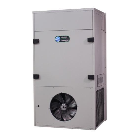
Models ECUA90/120
Description ........................... 5
Installation ......................... 11
Start-Up ............................. 20
Troubleshooting ................. 21
Maintenance ....................... 24
Warranty ............................ 25
P.O. Box 5104 • Cordele, Georgia 31010
2002 Hoover St. • Cordele, Georgia 31015
(229) 273-9558 • Fax (229) 273-5154
E-mail: icesales@airxcel.com • Internet: www.acice.com
Vertical Air Conditioners
Manufactured By:
, Inc.
®
Part Number 02118 12/2014 NEW
Advertisement
Table of Contents
Troubleshooting

Related Manuals for Industrial Climate Engineering ECUA90

Summary of Contents for Industrial Climate Engineering ECUA90
-
Page 1: Table Of Contents
Chapter 5 Maintenance ....... 24 Chapter 6 Warranty ......25 Manufactured By: Industrial Climate Engineering™ Division of AIRXCEL , Inc. ® P.O. Box 5104 • Cordele, Georgia 31010 2002 Hoover St. • Cordele, Georgia 31015 (229) 273-9558 • Fax (229) 273-5154 E-mail: icesales@airxcel.com •... -
Page 2: How To Use This Manual
How To Use This Manual This manual is intended to be a guide to Industrial Climate Engineering's line of vertical air conditioners. It contains installation, troubleshooting, maintenance, warranty, and application information. The information contained in this manual is to be used by the installer as a guide only. This manual does not supersede or circumvent any applicable national or local codes. - Page 3 WARNING • If the information in these instructions are not followed exactly, a fire may result causing property damage, personal injury or loss of life. • Read all instructions carefully prior to beginning the installation. Do not begin installation if you do not understand any of the instructions. •...
- Page 4 Table of Contents Chapter 5 Maintenance Scheduled Maintenance .........................24 Chapter 6 Warranty Limited Product Warranty ........................25 Illustrations Figure 1. Typical Electrical Schematic ....................10 Figure 2. Top Flange and Lifting Bracket Installation ................15 Figure 3. Wall Mounting Detail ......................16 Figure 4a.
-
Page 5: Chapter 1 Description
Chapter 1 Description & Specifications General Description Industrial Climate Engineering's (ICE) Environmental Control Units (ECU) are a series of vertical wall-mounted air conditioning systems that provide heating, cooling, and ventilation for electronic equipment shelters, process control centers, E-Houses, and other applications with high internal heat gains. -
Page 6: Air Flow, Weights And Filter Sizes
Weights and Filter Sizes Complete electrical and performance specifications and dimensional drawings are in the Product Data Sheet. Model Number ECUA90 ECUA120 Cooling BTUH 90,000 120,000 Rated Air Flow (CFM 3,500 4,000 @ Rated Conditions 0.30 0.30 Cooling rated at 95°F (35°C) outdoor and 80°F DB/67° WB (26.5°C DB/19.5°C WB) return air... -
Page 7: Electronic Control Board Mode Of Operation
Electronic Control Board Mode of Operation Normal 24 VAC power must be continuously applied to “R” and “C”. Upon a call for cooling “Y” and with the high pressure switch (HPS) closed, the compressor will be energized. (Note: See the delay on make feature.) The compressor will remain energized during the 3 minute timed low pressure by-pass cycle. -
Page 8: Optional Controls And Packages
reset is necessary to prevent harmful short-cycling. To reset switch, turn primary power off, then back on or turn thermostat system switch off, then back on. Low Pressure Switch The low pressure switch is mounted on the compressor suction line. It is designed to open if the refrigerant pressure drops to 40 PSIG;... -
Page 9: 1.8 Electrical Operation
Cabinet Color and Material The air conditioners are available in two standard cabinet colors -the standard grey with beige as an option. The standard cabinet’s sides, top and front panels are constructed of 16 gauge painted steel. Contact your ICE representative for color chips, custom colors and 316 stainless steel cabinets. 1.8 Electrical Operation The compressor and condenser fan are energized with a contactor controlled by a 24 VAC pilot signal. -
Page 10: Figure 1. Typical Electrical Schematic
Figure 1. Typical Electrical Schematic ECU 12/2014 NEW... -
Page 11: Chapter 2 Installation
D) When installing multiple units, please note the recommended clearances noted in Table 4. 4. Airflow Requirements: The maximum static pressure for the ECUA90 is 1.60 IWG (400 Pa) and 2.20 IWG (550 Pa) for the ECUA120. Keep duct lengths as short as possible. Do not obstruct airflow through the unit. -
Page 12: Electrical Supply
MIN. CLEARANCE BETWEEN MIN. SPACE MODEL SIDES (SINGLE UNIT) UNITS (TWO UNITS) ABOVE UNIT ECUA90/120 24 inches (76 cm) 18 inches (46 cm) 24 inches (61 cm) Table 4. Minimum Clearances 6. Codes: Make sure your installation conforms to all applicable electrical, plumbing, building, and municipal codes. - Page 13 Kit Components: Accessories: The package may include other factory-supplied items (optional): Description S/04581 CommStat 3 Controller, Solid State Lead/Lag Controller S/07846 CommStat 4 Controllers, Solid State Lead/Lag Controller 50123 Digital thermostat. 1 stage heat, 1 stage cool. 7 day programmable. Fan switch: Auto & On.
-
Page 14: Porting And Duct Work
Porting and Duct Work General Information Note: The following instructions are for general guidance only. Due to the wide variety of installa- tion possibilities, specific instructions will not be given. When in doubt, follow standard and accepted installation practices, or contact ICE™ for additional assistance. Wall Openings Measure the dimensions of the supply and return ports on the unit. -
Page 15: Installing The Lifting Brackets
Figure 2. Top Flange and Lifting Bracket Installation Installing the Lifting Brackets The ECU90/120 have lifting brackets that can be installed on the top of the side panels. These brackets allow the unit to be picked up thru lifting eyes in the brackets.The lifting brackets are shipped attached to the back panel of the ECU. -
Page 16: Electrical Connections
For units with electric heat, a one inch clearance is required around the duct extensions. The duct extensions must be constructed of galvanized steel with a minimum thickness of .019” as per the NFPA standards 90A & 90B. Figure 3. Air Conditioner Wall Mount Detail Electrical Connections WARNING ELECTRICAL SHOCK HAZARD... - Page 17 that the suction pressure drops and the discharge pressure rises when the compressor is energized. An alternate method of verification for self contained system with small critical refrigerant charges, where the installation of gauges may be objectionable, can be made by monitoring the temperature of the refrigerant lines at the compressor.
- Page 18 Low Voltage Wiring IMPORTANT. The following instructions are generic wiring instructions and may not be applicable for air conditioners with various options. Always refer to the wiring diagram in the air conditioner for the proper method to wire your unit. 1.
-
Page 19: Figure 4A. Thermostat Connection Diagram
Figure 4a. Thermostat Connection Diagram Figure 4b. CommStat 3 Wiring Diagram ECU 12/2014 NEW... -
Page 20: Chapter 3 Start-Up
Chapter 3 Start-Up Check-Out of Cooling Cycle Important: Be sure that the crankcase heater (if used) has been energized for at least 24 hours before starting the unit(s). Double-check all electrical connections before applying power. All air conditioners with scroll compressors running on 3Ø power must be checked for proper rotation during the initial start-up. -
Page 21: Chapter 4 Troubleshooting
Chapter 4 Troubleshooting Overview A comprehensive understanding of the operation of the air conditioner is a prerequisite to troubleshoot- ing. Please read the Chapter 1 for basic information about the unit. Our air conditioners are thoroughly tested before they are shipped from the factory. Of course, it is possible that a defect may escape undetected, or damage may have occurred during transportation. -
Page 22: Compressor Troubleshooting
PROBLEM/SYMPTOM LIKELY CAUSE(S) CORRECTION C. Unit cycles on high/low pressure 1. Loss or restriction of airflow. 1. Check blower assembly for proper operation. Look limit. for airflow restrictions, e.g.. the air filter. Check blower motor and condenser fan. 2. Restriction in refrigerant circuit. 2. -
Page 23: Control Board Diagnosis
3. Motor Winding Resistances: Using a digital volt-ohm meter (VOM), measure the resistance across the compressor windings as shown below. SINGLE THREE PHASE PHASE > R > R Resistance can be measured as shown above. Any deviation from above values could indicate a defective compressor. -
Page 24: Chapter 5 Maintenance
Chapter 5 Maintenance Scheduled Maintenance Industrial Climate Engineering strongly recommends that the air conditioner be serviced a minimum of twice a year – once prior to the heating season and once prior to the cooling season. At this time the filters, evaporator coil, condenser coil, the cabinet, and condensate drains should be serviced as described below. -
Page 25: Chapter 6 Warranty
Chapter 6 Warranty Limited Product Warranty If any part of your Industrial Climate Engineering™ Environmental Control Unit (ECU) fails because of a manufacturing defect within eighteen months from the date of original shipment by ICE or within twelve months from the date of original start-up, whichever is the earlier date, ICE will furnish without charge, EXW Cordele, Georgia, the required replacement part. - Page 26 NOTES ECU 12/2014 NEW...
Need help?
Do you have a question about the ECUA90 and is the answer not in the manual?
Questions and answers