Table of Contents
Advertisement
Quick Links
Advertisement
Table of Contents

Related Manuals for MIMAKI CG-100SRII


Summary of Contents for MIMAKI CG-100SRII
- Page 1 MIMAKI ENGINEERING CO., LTD. URL: http: // www.mimaki. co. jp/ D201949-15...
-
Page 2: Table Of Contents
TABLE OF CONTENS CAUTION ................. v CAUTION ................ v Requests ................. v FCC Statement (USA) ............. v Interference to televisions and radios ......v Foreword ................. vi About media ..............vi On This Operation manual ..........vi Features ................vii Safety Precautions ............viii Pictorial signs .............. - Page 3 Setting a sheet ............. 2-12 Setting a leaf sheet (cut sheet) ....... 2-15 How to Place the Roll Sheet ........2-17 Test cutting (plotting) ........... 2-20 Cutting (plotting) ........... 2-21 Setting the origin ............. 2-21 Start cutting (plotting) ..........2-22 Cut off the Sheet (Manual Cutting) ......
- Page 4 DATA CLEAR - Discontinue Plotting - ....3-52 Perform SAMPLE CUT to Find out the Cause of Cutting Error....3-53 Output the Setting List ..........3-54 Output the received data by the ASCII code [ASCII DUMP] ............3-55 Set the configurations with a computer ....3-56 Set each device number for USB connection ..3-58 Perform cutting a dotted line ........3-59 Perform plotting with perforated lines ......3-61...
-
Page 6: Caution
• In the case where MIMAKI-recommended cable is not used for connection of this device, limits provided by FCC rules can be exceeded.To prevent this, use of MIMAKI-recommended cable is essential for the connection of this plotter. -
Page 7: Foreword
Operation manual from our office. • You can also download the latest operation manual from our website. Reproduction of this manual is strictly prohibited. All Rights Reserved. Copyright © 2012 MIMAKI ENGINEERING Co., Ltd. -
Page 8: Features
Features The features of the plotter are described below. Together with the method of operation of the plotter explained in this manual, they help you understand how to use the machine properly. Mark Sensor The high accuracy mark-detection sensor enables the plotter to read the mark plotted on sheets automati- cally, compensate distances, set the plotting origin and correct paper skew. -
Page 9: Safety Precautions
Safety Precautions Pictorial signs Pictorial signs are used in this Operation manual for safe operation and for prevention of damage to the plotter. Pictorial signs and their meanings are given below. Read and fully understand before reading the text. Example of pictorial signs Failure to observe the instructions given with this symbol can result in death or serious inju- ries to personnel. - Page 10 WARNING Do not disassemble or remodel the plotter. Handling of the power cable • Never disassemble or remodel the plotter. • Use the supplied power cable. Take care Disassembly or remodeling can result in an not to damage, break or work upon the electric shock breakdown...
-
Page 11: Safety Labels
Safety Precautions CAUTION Be careful with the movable parts Caution with cutters • Do not touch the rolling grit roller; other- • Do not touch the cutter blade, which is very wise, you may hurt your fingers or tear off sharp. -
Page 12: How To Read This Operation Manual
How to Read This Operation Manual This manual provides the explanation about the displayed characters and used keys on the “Display Panel” in addition to the operation procedures. Proceed operations confirming them while using. This explains the out- line of functions. These are what we want you to know in advance. - Page 13 CHAPTER 1 Before Use This chapter describes the parts name and setting procedures before use. Where to install this machine ..........1-2 Configuration and function..........1-3 The Front ..................1-3 The Rear ..................1-4 Operation Panel ................1-5 Tray .....................1-6 Carriage ..................1-6 Pinch rollers and grit rollers ............1-7 Clamp ..................1-8 Sheet sensor ................1-8 Pen line rubber ................1-9...
-
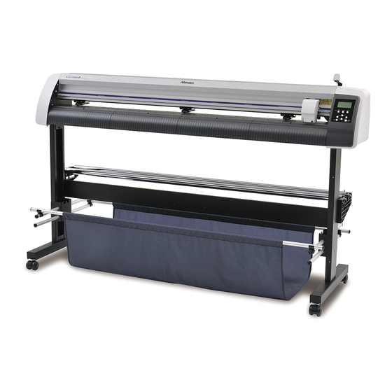
Page 14: Where To Install This Machine
1125 mm 38 kg CG-130SRII 1735 mm 580 mm 1125 mm 44 kg 1000 mm or more 2580 mm or more 500 mm 500 mm or more or more 1000 mm or more CG-100SRII : 2435 mm CG-130SRII : 2735 mm... -
Page 15: Configuration And Function
Configuration and function The Front Pinch roller The pinch rollers feed out the sheet while pressing it against Operation panel the grit rollers. ( P.1-7) This panel operates this machine and sets functions. Power switch P.1-5) The switch turns on/off the power.( P.2-8, 2-24) Clamp lever... -
Page 16: The Rear
The Rear Tray Small tools, such as a retractable Clamp pressure lever knife and other cutters, can be This lever adjusts the force placed on. by which the clamp is held. AC inlet P.1-8) power cable connected to the AC Sheet sensor inlet.( P.1-11) -
Page 17: Operation Panel
Configuration and function Operation Panel Display panel FUNCTION The display panel indicates tool conditions such as Use this key to enter function setting mode. speed, pressure and offset, tool coordinates, functions and error messages. JOG Key Each of these arrow keys shifts the carriage SHEET SET or sheet in the direction of the arrow or Use this key for detection of the... -
Page 18: Tray
Tray Small tools, such as a retractable knife, may be placed on the tray. Tray • However, keep a retractable knife or any other cutter out of reach of children since it can be dangerous. • Do not put any heavy object on the tray; otherwise, the cover may deform and come in contact with the carriage. -
Page 19: Pinch Rollers And Grit Rollers
Configuration and function Pinch rollers and grit rollers Align the pinch roller to the width of the sheet to be set, and move it to an appropriate position of the grit roller. The movement range of the pinch roller is as shown below. Move the pinch roller guessing the pinch roller guide marks as the measure. -
Page 20: Clamp
Clamp The clamp pressure can be changed in two levels using the clamp pressure lever. Select the higher or lower level of the clamp pressure that matches the sheet to be used. High mode Low mode Lower the clamp pressure lever. Raise the clamp pressure lever. -
Page 21: Pen Line Rubber
Configuration and function Pen line rubber Plotting and cutting are performed on the pen line rubber If you want to perform POUNCING and dotted line cutting, install the pen line. pen line rubber When performing POUNCING or HALF CUT Remove the pen line rubber. pen line rubber (1) Insert the flathead screwdriver or equivalent tool into the gap shown in the right. -
Page 22: Connecting The Cables
(2) Click [CD-ROM Contents] on the menu. (3) Open [usb11_installguid(en).pdf] for the plotter used in [Mimaki USB1.1 Driver] folder. RS-232C Cable Connection When you want to connect the RS-232C cable, you must observe the following notabilia. -
Page 23: Connecting The Power Cable
Connecting the cables Connecting the power cable After connecting the interface cable, you must connect the power cable. Connect the power cable with the plug outlet of the following power specifications. • Voltage : AC100 - 240V ± 10% • Frequency :50/60Hz •... -
Page 24: Menu Mode
Menu mode This plotter is provided with the following four modes: < NOT-READY > mode The plotter is in this mode until the media is detected. The keys other than the key are effective. REMOTE < LOCAL > mode The plotter enters this mode after the sheet detection. All the keys are effective. - Page 25 CHAPTER 2 Basic Operations This chapter describes the procedures and settings ranging from tool installation to cutting (plotting) operation. Operation flow..............2-2 Installing a tool..............2-3 Using a cutter ................2-3 How to Install a Ballpoint Pen .............2-6 Turning the power on ............2-8 Setting the tool conditions..........
-
Page 26: Operation Flow
Operation flow Installing a tool See "Installing a tool" ( P.2-3) Turning the power on See "Turning the power on" P.2-8) Setting the tool condi- See "Setting the tool conditions" P.2-9) tions Setting a sheet See "Setting a sheet" P.2-12) Test cutting (plotting) See "Test cutting (plotting)"... -
Page 27: Installing A Tool
Installing a tool For this device, you can use the following tools. Cutter : Select this to cut the image printed on a sheet and to create the cut letters with the cutting sheet. Pen (rollerball) : Select this to “trial-write” for confirming how to cut. Pouncing Pin : Select this to sketch the cutting line. - Page 28 Adjusting the protrusion of the cutter blade Adjust the cutter blade according to the types of the cutters and the sheet for use. After adjusting the protrusion of the cutter blade, set the cutting conditions and conduct test cutting to check the cutting quality.
- Page 29 Installing a tool How to install the cutter holder • Install the cutter holder to the tool holder of the carriage.Be sure to insert the cutter holder all the way in the tool holder. Rotate the knob to loosen the holder presser.
-
Page 30: How To Install A Ballpoint Pen
How to Install a Ballpoint Pen • When you want to use a commercially available ballpoint pen, you must use the pen of 8mm to 9mm in diameter. Image quality may depend on the pen. (Recommended ballpoint pen: the one available from Pentel Co., Ltd. with the product No.: K105-A, K105-GA) •... - Page 31 Installing a tool Insert until Insert the pen adapter with the pen into it is rested the tool holder. • Make sure that the brim of the pen adapter is rested on the tool holder. • Set the adapter in such a way that the fixing screw will not obstruct operation.
-
Page 32: Turning The Power On
Turning the power on • Before turning the power on, check that the pinch rollers have been raised. • Be sure to turn on the host computer before turning on the plotter. If this order is not correctly followed, the plotter can malfunction. •... -
Page 33: Setting The Tool Conditions
Setting the tool conditions You must set the tool conditions depending on the intended use. Kinds of the Tool Conditions The kinds of the tool conditions include cutting, plotting and pouncing conditions. See P.2-9 for the way of setting tool conditions. Kinds Description This is the tool conditions for using the cutter. -
Page 34: Set The Tool Conditions
Set the Tool Conditions Press the key several times to TOOL C U T 2 0 8 0 0 . 3 0 select a tool condition for setting. • The tool conditions include [CUT1 to CUT5], plotting condition (PEN), POUNCING condition (PIN), and cutting condition (HALF). - Page 35 Setting the tool conditions Press the key or ENTER/HOLD C U T 2 1 0 0 0 . 3 5 jog key to secure the setting value. • If you have selected the plotting condition (PEN) in the Step 1, consider SPEED: 40cm/s and PRESSURE: 60 to 80g as the reference value.
-
Page 36: Setting A Sheet
The pinch rollers and grit rollers hold the sheet in position. Locate the pinch rollers so that they match the sheet to be used. Pinch roller Clamp lever Grit roller Sheet width inch CG-100SRII 90 to 1250 3.55 to 49.20 CG-130SRII 90 to 1550 3.55 to 61.00 2-12... - Page 37 In normal mode, the area defined with the inner edges of the pinch rollers is detected. P.3-39) The origin is set at the lower The origin is set at the right corner of the area. center of the area. CG-100SRII 1.07m X 51m 1.07m X 3m CG-130SRII 1.37m X 51m 1.37m X 3m...
- Page 38 Method of detecting a sheet When a sheet of media is set, the following two displays will appear alternately on the LCD panel. Align to the direction of the set sheet, and press the jog keys R O L L < R > L E A F R O L L L E A F R set...
-
Page 39: Setting A Leaf Sheet (Cut Sheet)
Setting a sheet Setting a leaf sheet (cut sheet) Press the key to switch to SHEET SET R O L L < > L E A F NOT READY mode. • You need not to do so if it ia already in the NOT READY mode. - Page 40 Press the jog key to select “LEAF”. • For "Sheet detection" ( P.2-13) • : In the case the sheet is loaded from the rear : In the case the sheet is loaded from the front Press the jog key to select P I N C H R O L L .
-
Page 41: How To Place The Roll Sheet
Setting a sheet How to Place the Roll Sheet If you want to use the roll sheet, you must mount the roll-placing table. Move down the clamp lever to the rear. Set the roll bars on the roll stays. Projection •... - Page 42 Retain the roll sheet with the roll Roll holder holders. • Move the roll holders to both ends of the roll,respectively, and secure them by tighteningthe screws. • Locate the roll holders 2 to 3 mmaway from the respective roll ends.If the roll holders are fixed pressedagainst the roll ends, there may be acase Do not place where the roll cannot turn andthus the sheet cannot...
- Page 43 Setting a sheet Press the jog key to select P I N C H R O L L . : 3 number of pinch rollers to be used. • When [ROLL. SELECT] is set to [ON], selectthe number of pinch rollers to be used. Displays the detected Press the key to start to...
-
Page 44: Test Cutting (Plotting)
Test cutting (plotting) Execute test cutting (plotting) to confirm the tool conditions. In the test cutting, the plotter cuts two squares. • When the cutter blade is worn and dull, you can use it temporarily by enhancing the value of PRESSURE. -
Page 45: Cutting (Plotting)
Cutting (plotting) You can start cutting (plotting) after completion of setting up a tool, a sheet and the tool conditions. • Check the following settings before cutting (plotting). Setting of the origin ( P.2-21) Setting of the command origin ( P.3-69) Switching between commands ( P.3-69) -
Page 46: Start Cutting (Plotting)
Start cutting (plotting) After completion of setting the origin, C U T 1 R E M O T E press the key. REMOTE • The display changes to REMOTE. Send the data to the plotter. C U T 1 1 3 5 6 K B •... -
Page 47: Cut Off The Sheet (Manual Cutting)
Cutting (plotting) Cut off the Sheet (Manual Cutting) Hold the sheet by hand. • Make sure to hold firmly to avoid the sheet raiseup. Slot Cut the sheet. • Cut the sheet with a cutter knife in the slot on the platen. -
Page 48: Turning The Power Off
Turning the power off When plotting is completed, press the “ O ” side of the power switch to turn the power off. • Once the power is turned off, wait at least five seconds before turning the power on again. Confirm that the plotter is not receiving C U T 1 R E M O T E... - Page 49 CHAPTER 3 Useful Function This chapter describes the setting procedures of each functions, and how to operate the plotter usefully. Functions in the Jog Mode ....3-2 Change the cutting (plotting) order ... 3-46 Setting the origin ........3-2 Set SORTING ........3-47 Two-point axis alignment ......
-
Page 50: Functions In The Jog Mode
Functions in the Jog Mode Press the jog key in the local mode, and then you can enter the jog mode, where you can perform the following settings. Reference Function names Contents page Setting the origin Set the point from which the plotter will start cutting (plotting). P.3-2 Two-point axis If a ruled sheet is set, align the horizontal and vertical axes with the... -
Page 51: Two-Point Axis Alignment
Functions in the Jog Mode Two-point axis alignment If a ruled sheet is set, align the horizontal and vertical axes with the Compensation point appropriate lines on the sheet. Correct the axial inclination (θ) by setting a compensation point in combination with the origin. -
Page 52: Cutting Area
Cutting area Set the area in which the plotter performs cutting Point UL (plotting). The area that has a diagonal line extending from the origin to a given UL (upper left) point is the available cutting area. The cutting area setting will be cleared by performing sheet detection again. -
Page 53: Digitization Operation
Functions in the Jog Mode Digitization operation The coordinates of the plotted figure relative to the origin are displayed on the host computer. Upon receiving the digitization command (DP;) from the host computer, the plotter is ready for digitization operation. To conduct digitization, install a sheet with patterns to select points on it. -
Page 54: Set The Distance Compensation
Set the distance compensation When cutting is to be performed along a long length, the cut length may significantly differ from the data value, depending on the thickness of the sheet. Additionally, the diameter difference between the grit rollers may cause a significant difference in the sheet feeding distance between the right side and the left side. This function compensates those differences. - Page 55 Set the distance compensation Setting procedure Press the key in the local mode. TOOL C U T 1 0 5 0 0 . 3 0 • Tool conditions are displayed with the cursor blinking at the [SPEED] value. Press the jog key C U T 1 0 5 0 0 .
- Page 56 Change the reference length in the B direction (horizontal direction) with the jog key • If you change the reference length in the B direction, the distance compensation value (B) will be cleared. Press the key to determine ENTER/HOLD D R A W S H I F T = 0 m m the reference length in the B direction.
- Page 57 Set the distance compensation If the reference value and the measured A R = 1 . 0 A L = 0 . 0 value differ from each other, change the compensation value with the jog Press the key to determine ENTER/HOLD A R = 1 .
-
Page 58: Perform Multiple Cuttings
Perform Multiple Cuttings This function performs cutting (plotting) for the received data on two or more sheets.(Maximum 999 cuttings) The origin at executing the multiple sheet cutting. Copy interval (Manual setting) The origin at terminating the multiple sheet cutting (Automatically established) •... - Page 59 Perform Multiple Cuttings • If the multiple sheet cutting is executed immediately after cutting in the remote mode, cutting (plotting) will be overlapped. To avoid this trouble, be sure to set the new origin. • While the plotter is executing the multiple sheet cutting, it ignores data sent from the computer. •...
-
Page 60: Cut Out Data With Registration Mark
Cut Out Data with Registration Mark Create registration marks on an output image that you want to make a seal, and then the plotter detects them to cut it out. There are following two types of registration marks. Registration mark: Type 1 Registration mark: Type 2 •... -
Page 61: Precautions In Inputting Data With Registration Marks
Cut Out Data with Registration Mark Precautions in inputting data with registration marks There are some limitations on preparing data with registration marks. In order to make full use of this function, read the following instructions carefully and prepare data with registration marks properly. - Page 62 No-plotting area around the registration marks An area around a registration mark (from the mark origin to the mark size area) is a non-plotting area. There must be no data plotted or stain in this area; otherwise, a wrong origin may be detected or a mark read error can occur.
- Page 63 Cut Out Data with Registration Mark The size of, and the distance between, registration marks The size (B) of a registration mark suited for the distance (A) between the marks is as shown below. If the mark size (B) is too small relative to the distance (A), the marks may not be detected correctly. Be sure to prepare the registration marks with an appropriate size.
- Page 64 Recommended size of the area defined with a set of four registration marks It is recommended that the size of the area defined with a set of four registration marks is in the range of A4 size (210 mm x 297 mm) to A3 size (297 mm x 420 mm). If you follow this recommendation, you can minimize wasteful spaces and arrange the designs efficiently.
- Page 65 Cut Out Data with Registration Mark Precautions on registration mark detection Observe the following precautions on registration mark detection. • To ensure that the distance between registration marks is equal to the cutting length, input the distance between the printed marks found by the mark detecting function. (DIST.REVI P.3-20) In this case, scale compensation between the registration marks overrides distance compensation.
-
Page 66: Set For Detecting The Registration Marks
Set for Detecting the Registration Marks When you want to cut the data with registration marks, you must set the following without fail. Press the key in the local FUNCTION D A T A C L E A R < E N T > mode. - Page 67 Cut Out Data with Registration Mark Press the key. ENTER/HOLD Press the jog key to select the set values. • See pages P.3-19 through P.3-22 for the contents of each setting item. Press the key to confirm the value. ENTER/HOLD イ...
- Page 68 DIST.REVI Select “OFF” when using FineCut. Setting Description The plotter will not perform any scale compensation. BEFOR With this setting, enter the scale compensation values and the trapezium compensation value before executing the registration mark detection. P.3-24 , P.3-27) Since the distance between registration marks is entered beforehand, rapid movement is expected when detecting.
- Page 69 Cut Out Data with Registration Mark MARK FORM Setting Description Select either one of the following types of registration marks. TYPE1 TYPE2 Mark: TYPE1 Mark: TYPE2 COPIES A ( UP ), COPIES B ( LEFT ) Setting Description Effective when the same pattern is multi-printed at regular intervals. 1 ~...
- Page 70 SKEW CHECK Setting Description Set the allowable range of the sheet feeding error when performing continuous 0 ~ 99mm copy. During continuous copying on a roll sheet, copies may be misaligned little by little because of sheet skewing. If the error in the B-axis coordinate of the TP1 mark has exceeded the allowable range, cutting operation is temporally stopped.
-
Page 71: Method Of Detecting Registration Marks
Cut Out Data with Registration Mark Method of detecting registration marks Registration marks are detected in two different ways; full-automatic detection and semi-automatic detection. Use the semi-automatic function when the TP1 is not located at the bottom right of the sheet, or when the supplied FineCut is to be used as the cutting software. - Page 72 Full-automatic detection of marks Use this function to correct the error in the detected length between registration marks as compared with the printed length between registration marks. For this purpose, measure the length A and B on the data beforehand. Measure the length between the registration marks.
- Page 73 Cut Out Data with Registration Mark Set with the jog key A ( 1 - 2 ) = * * * . * • Press the key. And the plotter moves ENTER/HOLD to the next scale compensation setting. • If [MARK DETECT] is set to [2ptA], the display for B ( 1 - 3 ) = * * * .
- Page 74 Detecting procedure ( [DIST.REVI.] Setting value is “AFTER”) • Be sure to set the sheet in the rear. Follow steps 1 to 3 of "Detecting procedure ( [DIST.REVI.] Setting value is “BEFOR”)" ( P.3-24) Press the key. ENTER/HOLD R O L L <...
- Page 75 Cut Out Data with Registration Mark Semi-automatic detection of registration marks When TP1 cannot be located at the position where it can be detected full-automatically or when no registration mark can be detected full-automatically, perform registration mark detection semiautomatically. Pinch roller Detecting procedure ( [DIST.REVI.] Setting value is “BEFOR”) Load the sheet Load the sheet and move down the clamp lever to the front.
- Page 76 Press the key. ENTER/HOLD S E A R C H S T A R T P O S • The scale compensation display appears. (The right figure shows the 4-point detection display as an example.) A ( 1 - 2 ) = * * * . * Make setting with the jog key A ( 1 - 2 ) = * * * .
- Page 77 Cut Out Data with Registration Mark Detecting procedure ( [DIST.REVI.] Setting value is “BEFOR”) Follow steps 1 to 3 of "Detecting procedure ( [DIST.REVI.] Setting value is “BEFOR”)" ( P.3-27) Press the key. ENTER/HOLD * * M A R K D E T E C T * * •...
- Page 78 Detect a registration mark automatically after the sheet is detected Set the automatic registration mark search function performed after the sheet is detected. If both of the registration mark detection and the registration mark search is valid, the function will search the registration mark automatically after the sheet is detected.
- Page 79 Cut Out Data with Registration Mark Press the key. ENTER/HOLD S C A N W I D T H : 1 0 c m Press key to select the S C A N W I D T H : 2 0 c m scan width.
-
Page 80: Confirm The Following When Failed In Cutting Correctly
Confirm the following when failed in cutting correctly. Check the sensor for the registration mark detection Prepare the sheet on which the registration mark is printed. • If you move the head and sheet manually, you cannot perform the right response check. Be sure to perform it via the following operations. - Page 81 Cut Out Data with Registration Mark Press the key to terminate the jog mode. • The plotter returns to the local mode. Press the key. FUNCTION D A T A C L E A R < E N T > Select [MARK sensor] by pressing the M A R K s e n s o r <...
- Page 82 Detect operation Scan in the B direction (plus direction) to detect the line. • The buzzer sounds when the line is detected. If the line is not detected, the buzzer does not sound. Scan in the B direction (minus Minus direction) to detect the line.
- Page 83 Cut Out Data with Registration Mark Correct the light pointer position If the plotter fails to recognize any registration mark properly, the possible cause is an error in the positional relationship between the MARK sensor and the light pointer. In this case, adjust the position of the light pointer. Install a cutter in the tool holder.
- Page 84 By pressing the jog keys , adjust the light pointer position so that the center of the light pointer is in alignment with the center of the cross pattern. Press the key. ENTER/HOLD C U T 1 0 5 0 0 .
- Page 85 Cut Out Data with Registration Mark Alignment of MARK SENSOR The offset value of the cutter and the mark sensor can be adjusted. Set the sheet on which the register mark is printed. Usable on Firmware Ver.1.1 or lator. Install a cutter in the tool holder. Confirm that the plotter is in the local C U T 1 0 5 0...
- Page 86 Cut Out Data with Registration Mark Press the key. ENTER/HOLD A = 0 . 0 B = 0 . 0 • The offset value of the cutter and the mark sensor can be adjusted. • Set the sheet on which the register mark is printed. Misaligned by +0.2 mm from the center line of the register mark (...
-
Page 87: Expand The Cutting (Plotting) Area
Expand the cutting (plotting) area You can reduce the dead space to expand cut (picture drawing) area (EXPANDS function). The dead space is reduced by 10mm at the left and right. EXPANDS: OFF EXPANDS: ON Pinch roller (left) Pinch roller (right) When the sheet is set in the rear Set the EXPANDS function to ON. - Page 88 Expand the cutting (plotting) area Press the key. ENTER/HOLD E X P A N D S : O F F the jog keyPress key to E X P A N D S : O N select “ON.” Press the key. ENTER/HOLD Press the key twice for terminating this function.
-
Page 89: Switch The Cutting (Plotting) Direction
Switch the cutting (plotting) direction This function sets the location of origin and direction of the axes of coordinates according to the application software to be used. (ROTATION function) Rotating function : OFF Rotating function : ON • After the sheet detection, the Origin Origin carriage will stop at the origin. -
Page 90: Coordinate System
Switch the cutting (plotting) direction Press the key. ENTER/HOLD Press the key twice for terminating this function. Coordinate system The plotter has four different coordinate systems established by combinations of the sheet setting direction and the rotation of the coordinate axes. <... -
Page 91: Perform Division Cut
Perform DIVISION CUT. Setting the DIVISION CUT allows you to divide and cut data larger You can divide and cut the part than the sheet width (DIVISION CUT function). that runs off the edge. • With the DVISION CUT function, you can use the following convenient functions too. - Page 92 Press the to select “ON.” D I V I S I O N c u t : O N Press the key. ENTER/HOLD F R A M E C U T : O F F Press the jog key to select F R A M E C U T : O N...
-
Page 93: Cut Data Via Division Cut
Perform DIVISION CUT. Cut Data via DIVISION CUT. Send data from the host computer to the plotter. Available area Origin • If the data exceeds the available cutting area, the display shown at right will appear. O F F S C A L E When cutting completes, the plotter * * D I V I S I O N * * X X s... -
Page 94: Change The Cutting (Plotting) Order
Change the cutting (plotting) order You can reorder or sort the cut data that has been sent from the host computer to change the order for cutting (SORTING function). Suppose that there is data that you want to cut just like drawing a picture with a single stroke, according the order in which data is sent from application software. -
Page 95: Set Sorting
Change the cutting (plotting) order Set SORTING . Press the key in the local FUNCTION D A T A C L E A R < E N T > mode. Press the jog key to select S E T < E N T > [SET UP] . - Page 96 Press the jog key to select A R E A 5 0 0 the setting of [AREA] . • Setting values : OFF or 10 to 5,100cm (in 10cm increment) Press the key for setting, and press the key. ENTER/HOLD •...
-
Page 97: Sorting Sequence
Change the cutting (plotting) order Sorting sequence Data transmission is started. C U T 1 2 K B • The size of unprocessed data in the receiver buffer is displayed. • Cutting is not performed. The processed line segments are stored in the sorting buffer. After completion of data transmission, P L O T the display shows the waiting time for... -
Page 98: Other Useful Functions
Other Useful Functions Feed the paper Before starting cutting (plotting), feed the sheet manually by the length to be used. In addition, by feeding the sheet beforehand, you can check for a skew of the sheet or prevent skew while cutting (plotting) the long data. •... -
Page 99: Hold
Other Useful Functions HOLD If a sheet goes out of alignment while long data is being cut Data after the correction (picture-drawn), you can temporarily hold the cut for fixing the of sheet displacement misalignment of the sheet. • When correcting the displacement of the sheet, Cut before the sheet move neither the carriagenor the pinch rollers. -
Page 100: Data Clear - Discontinue Plotting
DATA CLEAR - Discontinue Plotting - Execute the DATA CLEAR function to discontinue cutting (plotting) for data. If you do not perform DATA CLEAR, the plotter will perform cutting for the received data when it is returned to the remote mode. Once DATA CLEAR is executed, the plotter will perform cutting (plotting) for new data, if received after the plotter is set to the remote mode. -
Page 101: Perform Sample Cut To Find Out The Cause Of Cutting Error
Other Useful Functions Perform SAMPLE CUT to Find out the Cause of Cutting Error. In case that normal data cutting cannot be performed etc., perform SAMPLE“Cut” cutting with the sample stored in this plotter to find out the cause of cutting error. -
Page 102: Output The Setting List
Output the Setting List You can keep this plotted sheet for your future reference or transmit this document by facsimile when you contact your local distributor for maintenance. Set a A4-size discard sheet in a longitudinal direction ( P.2-15) , and replace the tool with “pen”... -
Page 103: Output The Received Data By The Ascii Code [Ascii Dump]
Other Useful Functions Output the received data by the ASCII code [ASCII DUMP] This function makes the host computer send data to the plotter, makes the plotter plot the communication conditions of the interface through which it receives the data, and makes the plotter plot the data in ASCII format. -
Page 104: Set The Configurations With A Computer
Set the configurations with a computer Set the configurations with a computer Set the communication condition with the RS-232C interface and the USB identification number.Settings of the communication conditions differ with the command (AUTO, MGL-I c1 or MGL-II c)specified using the command change-over function. - Page 105 Other Useful Functions Press the key.. ENTER/HOLD Press the jog key to select the set values. • See pages P.3-57 for the contents of each setting item. Press the key to confirm the value. ENTER/HOLD イ When you want to terminate this procedure, press the key twice.
-
Page 106: Set Each Device Number For Usb Connection
Set each device number for USB connection When two and more plotters are connected to a host computer with USB cables, give different plotter numbers to the plotters, respectively. Press the key in the local FUNCTION D A T A C L E A R <... -
Page 107: Perform Cutting A Dotted Line
Other Useful Functions Perform cutting a dotted line When cutting the sheet according to data, the plotter cuts Cutter the design in broken lines without cutting it out. Sheet • For the broken-line cutting, use the cutter (model: SPB-0001, a set of three cemented carbide blades) that is optionally available. - Page 108 Press the key. ENTER/HOLD H A L F l e n g t h : 0 . 5 m m Press the jog key to select H A L F l e n g t h : 2 . 5 m m the length of half cutting.
-
Page 109: Perform Plotting With Perforated Lines
Other Useful Functions Perform plotting with perforated lines You can use a pin to perforate along the outline of data (POUNCING function). You can mark the perforated sheet with a marker pen, spray or others to use it for positioning of construction and hand-written signboard. - Page 110 Set POUNCING function. Press the key in the local FUNCTION D A T A C L E A R < E N T > mode. Press the jog key to select S E T < E N T > [SET UP] . Press the key.
-
Page 111: Make The Media Without Uncut Area
Other Useful Functions Make the media without uncut area By over wrapping the start point and the end point arbitrarily, you can make the media without uncut area. Specify the over cut function (valid/invalid) and the length of the over cut. If Over cut the length of the over cut is set, when cut starts, cut will be performed from part... - Page 112 Press the key. ENTER/HOLD Press the key twice for terminating this function. 3-64...
-
Page 113: Select The Number Of Pinch Roller To Use
Other Useful Functions Select the number of pinch roller to use Set the number f pinch roller to detect when the sheet detection. Press the key in the local FUNCTION D A T A C L E A R < E N T > mode. - Page 114 Other Useful Functions Press the key twice for terminating this function. • If “2” is set to “PINCH ROLL” and “OFF” is set to “ROLL. SELECT”, only 2 pinch rollers will be detected at sheet detection. • When using wider sheet, you may wish to limit the number of pinch roller because you do not want to leave the trace of the roller on the sheet.
-
Page 115: Miscellaneous Settings
Miscellaneous Settings Switch the display language You can select the display language from the following seven kinds (it is set to “English” when you purchase this plotter). Languages you can select : Japanese, English, German, French, Spanish, Italian, Portuguese Press the key in the local FUNCTION D A T A... -
Page 116: Other Convenient Settings
Other Convenient Settings Change the settings according to your use. Press the key in the local FUNCTION D A T A C L E A R < E N T > mode. Press the jog key to select S E T <... - Page 117 Miscellaneous Settings Setting List Function Outline Setting values name When cut the data with Mark registration marks, you must set See P.3-18. Detect without fail. This is to automatically switch the command AUTO according to the command specifications of the receiving data. Command Switch the unit of moving amount This is selected when the plotter receives the...
- Page 118 Function Outline Setting values name This is to set the speed of sheet and carriage movement when the tool is 5,10,20,30,4 When setting to AUTO, the speed value set 0,50,60, Up Speed in the TOOL conditions is used as the up- Setting the speed lower makes the AUTO speed (but the lowest speed is 10cm/s).
- Page 119 Miscellaneous Settings Command Switching • Changing the setting value will clear the data in the receiver buffer. • With a large size of data, the [AUTO] mode may not function normally. In that case, change the setting to MGL - Ic1 or MGL-IIc. •...
- Page 120 Priority Setting of priority is available with MGL-II c commands.Specifically, setting of priority is applied to the follow- ing commands. Pen selection command Pen lowering speed setting command Pen lifting speed setting command Acceleration setting command Pen pressure setting command FS;、...
- Page 121 Miscellaneous Settings Dummy Cutting The plotter executes dummy cutting in front of the pinch roller that is located on the side closer to the current location of the carriage. Set the dummy cut function to OFF if you do not want to dummy-cut Pinch Roller the sheet that is to be used with characters cut out.
-
Page 122: Reset The Setting Values To The Initial State
Miscellaneous Settings Reset the setting values to the initial state. Press the key in the local FUNCTION D A T A C L E A R < E N T > mode. Press the jog key to select S E T <... - Page 123 CHAPTER 4 In Case of Trouble This chapter describes the actions to be taken when the plotter develops any trouble or displays an error message. Before taking a phenomenon as a trouble ......4-2 Troubles for which error messages are given on the LCD ............4-4 Error message ................4-4 Status message ................4-8...
-
Page 124: Before Taking A Phenomenon As A Trouble
Before taking a phenomenon as a trouble Take appropriate remedies according to the table below. If still the problem cannot be solved, contact MIMAKI or its dealer. Phenomenon Cause Remedy Connect the power cable to the The power cable is not Power does not turn on. - Page 125 Before taking a phenomenon as a trouble Phenomenon Cause Remedy When a long leaf sheet is to be cut, take care not to bend the sheet while feeding or cutting it and do not put any extra load on The sheet was bent and came the sheet.
-
Page 126: Troubles For Which Error Messages Are Given On The Lcd
Troubles for which error messages are given on the LCD Error message Error messages are shown as error numbers. Take an appropriate remedy according to the table below. And if the remedy does not work, contact your distributer or an sales office of MIMAKI. Error message Cause Remedy... - Page 127 P.3-18 Confirm the status and the settings described above. If still no registration mark is detected, contact your distributor or a sales office of MIMAKI. The origin point was detected outside Arrange the registration marks inside ERR37 MARK ORG the cutting area.
- Page 128 In case no registration mark is detected even by retrying the detection several times, contact your distributor or a sales officeof MIMAKI. An excessive load was applied to the Turn the power off once and turn it on ERR40 MOTOR A sheet feeding motor.
- Page 129 MIMAKI. Check whether the pen line rubber is not extremely worn or there is neither lifting nor change of shape. Check whether a foreign material adheres on the pen line rubber.
-
Page 130: Status Message
Status message The messages given below appear in the remote mode. They do not indicate errors but require an appropriate action. Message Cause Remedy A press on the key will cause REMOTE CUT1 * REMOTE * The plotter is in the remote mode. the plotter to enter the local mode. - Page 131 If the same message appears, contact REMOTE turning the power on. your distributor or a sales office of MIMAKI. Cutting cannot be continued, since roll End of the sheet is detected while sheet has ended. detecting a mark or cutting roll sheet.
- Page 132 4-10...
- Page 133 CHAPTER 5 Appendix The appendix describes the replacement procedure for the cutter blade and the specifications of the plotter. Specifications of the main unit........... 5-2 Repeatability condition ..............5-3 Cutter blade ................5-4 Replacing the cutter ..............5-4 Adjusting the cutter blade ............5-4 Replacing the cutter other than supplied one ......5-5 Adjusting blade edge of cutter other than supplied one ....5-5 Note slip................
-
Page 134: Specifications Of The Main Unit
The image quality is not guaranteed because the pen tip position differs depending on the pen in use. *6: With the USB connection, the ESC type commands among the MGL-llc commands cannot be used. *7: The values are based on MIMAKI's measurement conditions. -
Page 135: Repeatability Condition
Specifications of the main unit Repeatability condition Plotter conditions • When using a exclusive roll-placing table. • The clamp pressure must be set to “HIGH” . • The specified repeatability may not be guaranteed depending on the material of the sheet to be cut or ink jet media, Sheet setting conditions •... -
Page 136: Cutter Blade
If the cutter is chipped or blunt, replace it with a new one. (Accessorry parts number: SPA-0030) New cutter (low-pressure blade set for PVC sheets: Model SPB-0030) are available from your distributor or MIMAKI's sales office. Name of product Product No. -
Page 137: Replacing The Cutter Other Than Supplied One
Cutter blade Replacing the cutter other than supplied one Lock nut Loosen the lock nut, and pull the Adjusting knob adjusting knob out of the holder. Insert the cutter into the adjusting knob using tweezers. Tighten the lock nut. Adjusting blade edge of cutter other than supplied one After the completion of adjustment, be sure to set cutting conditions and perform test cutting to check the cutting quality. -
Page 138: Note Slip
Note slip When changing the sheet for cutting (plotting), distance correction may be required depending on the sheet thickness. ( P.3-6) In that case, the following note slip is useful to note down the sheet name and the distance correction value. Sheet Name: Sheet Name: Sheet Name:... -
Page 139: Function Flowchart
Function Flowchart Functions invoked with the specific keys REMOTE Key: CUT 1 2 0 0 5 0 0 . 3 0 CUT 1 * REMOT E * Local mode SHEET SET Key: CUT 1 2 0 0 5 0 0 . 3 0 ROL L <... - Page 140 TOOL Key (Settings of Tool conditions) : CUT 1 * REMOT E * CUT 1 2 0 0 5 0 0 . 3 0 Remote mode Present tool setting CUT 1 2 0 0 5 0 0 . 3 0 CUT 1 2 0 0 5 0 0 .
-
Page 141: Functions Invoked With The Jog Mode (Jog Keys)
Function Flowchart Functions invoked with the jog mode (jog keys) Setting an origin CUT 1 2 0 0 5 0 0 . 3 0 0 . 0 0 . 0 5 . 0 1 0 . 0 Local mode A = * * * * B = * * * * * * OR I G I N * * Cutting area... -
Page 142: Functions
Functions CUT 1 2 0 0 5 0 0 . 3 0 DA T A C L EAR < ENT > Local mode SQUARE CUT < ENT > N o . COP I ES < ENT > N o . COP I ES I NT ERVA L 1 ~... - Page 143 Function Flowchart Enable to setting [MARK DETECT] is not [OFF] D I S T . REV I . : A F T ER S I Z E : 1 0mm o f f s e t A 0 . 0mm o f f s e t B 0 .
- Page 144 Followed Followed SE T UP < ENT > POUNC I NG < e n t > POUNC I NG : OF F ON , OFF PR I OR I T Y < e n t > PR I OR I T Y : OF F ON , OFF D I S T ANCE...
- Page 145 Function Flowchart F EED SPEED : 1 0 1 to 20 (cm/s) Enable to setting [SORTING] is [ON] AUTO F EED : ON AREA : OF F ON , OFF OFF , 10 ~ 5100 ROL L . S L ECT : ON ON , OFF SCAN WI DTH : 1 0 c m S e a r c h R a n g e : 1 0 c m...
- Page 146 Followed Followed MARK s e n s o r < ENT > SENSOR CHK < e n t > S I Z E : 4 0mm 4 ~ 40 mm PO I NTOR OF S < e n t > A = 0 .
- Page 147 Function Flowchart FORM : T YPE 1 TYPE1 , TYPE2 5-15...
- Page 148 5-16...
- Page 149 D201949-15-29022012...
- Page 150 © MIMAKI ENGINEERING CO., LTD.2012 FW : 2.4...
Need help?
Do you have a question about the CG-100SRII and is the answer not in the manual?
Questions and answers