
Related Manuals for Fisher & Paykel DishDrawer DD60S 7


Summary of Contents for Fisher & Paykel DishDrawer DD60S 7
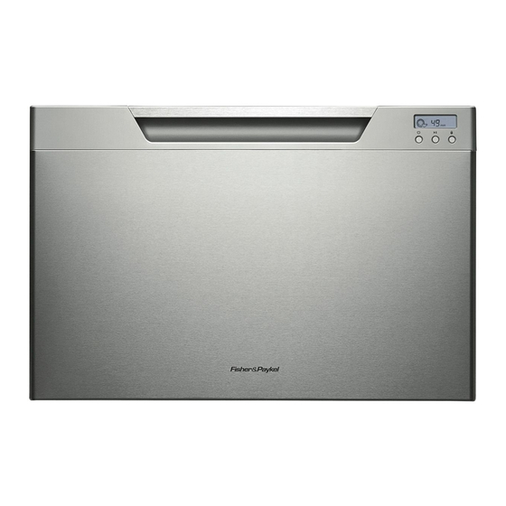
- Page 1 INSTALLATION INSTRUCTIONS DishDrawer dishwasher DD60S 7 & DD60ST 7 models NZ AU GB IE 590200D 04.13...
- Page 2 FOLLOW THE INSTALLATION SEQUENCE RELEVANT TO YOUR MODEL TALL HEIGHT SINGLE MODELS STANDARD HEIGHT SINGLE MODELS ONLY AVAILABLE IN NZ AU ONLY AVAILABLE IN GB IE ONLY AVAILABLE IN NZ AU ONLY AVAILABLE IN GB IE Classic Classic Designer Integrated with remote control Integrated with badge control Designer Integrated with remote control Integrated with badge control DD60SC(H)X7...
-
Page 3: Important Safety Instructions
SAFETY AND WARNINGS - ALL MODELS IMPORTANT SAFETY INSTRUCTIONS! WARNING! Installation of this dishwasher requires basic mechanical and electrical skills. Electrical shock hazard Be sure to leave these Instructions with the Customer. Before installing the dishwasher, remove the house fuse or open the circuit Installation must comply with your local building and electricity regulations. - Page 4 PARTS SUPPLIED - ALL MODELS Side mounting Clamp (1) Drain hose Drain hose Wire clip (1) Phillips 38 mm Rubber Moisture bracket kit support (1) joiner (1) 16 mm bottom washer for protection (for securing (for securing (A and B) (2) screws (7) fixing screws inlet hose (1)
- Page 5 ADDITIONAL PARTS SUPPLIED WITH INTEGRATED MODELS External Venting kit (1) Panel bracket (1) Panel mounting Integrated rectangular badge (1) (attached to screws (6) (Satin chrome supplied) product) supplied with Integrated models with remote only supplied with Integrated models with badge only...
-
Page 6: Product Dimensions
PRODUCT DIMENSIONS Plan Side Product dimensions (mm) STANDARD HEIGHT MODELS TALL HEIGHT MODELS overall height of product (incl. front panel height) overall width of product overall depth of product (excl. handle) depth of chassis (to back of front panel) maximum extension of drawer (excl. -
Page 7: Cabinetry Dimensions
CABINETRY DIMENSIONS Plan Side Cabinetry dimensions (mm) STANDARD HEIGHT MODELS TALL HEIGHT MODELS inside height of cavity min. 412 min. 412 min. 412 min. 412 inside width of cavity inside depth of cavity min. 560 min. 560 min. 560 min. 560 min. - Page 8 INTEGRATED MODELS WITH REMOTE ONLY - CUSTOM FRONT PANEL CALCULATIONS FRONT PANEL SPECIFICATIONS min. 2 mm 16 -20 mm panel thickness Maximum weight of panel: 9 kg Adequately sealed to withstand moisture (50 C @ 80% RH). Because of it being a hot and wet environment generally, the back and sides of the panel should be completely sealed with a waterproof vapour barrier (ie polyurethane) to prevent damage to the panel.
- Page 9 INTEGRATED MODELS WITH BADGE ONLY - CUSTOM FRONT PANEL CALCULATIONS FRONT PANEL SPECIFICATIONS min. 2 mm 16 -20 mm panel thickness Maximum weight of panel: 9 kg Adequately sealed to withstand moisture (50 C @ 80% RH). Because of it being a hot and wet environment generally, the back and sides of the panel should be completely sealed with a waterproof vapour barrier (ie polyurethane) to prevent damage to the panel.
-
Page 10: Cavity Preparation
CAVITY PREPARATION Important! BENCHTOP The power outlet must be located in a cabinet adjacent to the dishwasher cavity. Moisture 10 mm 220-240 VAC min. 4.8 A protection tape must be applied. Water Connection Recommended COLD (Maximum 60°C). These marks indicate ¾... - Page 11 INTEGRATED MODELS WITH REMOTE ONLY - PREPARATION FOR EXTERNAL VENTING THROUGH SAME CABINET Services can be located either side of dishwasher External Venting kit (1) Shelf cutouts max. 5 mm VENT HOSE ø 60 mm min.100 mm SERVICES 220 mm Important! 100 mm To prevent pooling of condensation from the vent hose, a...
- Page 12 MAXIMUM DISTANCE OF HOSES & CORD FROM CHASSIS EDGE Left hand side Right hand side Drain hose - 2000 mm Drain hose - 2000 mm Drain hose - 1800 mm Drain hose - 1800 mm Inlet hose - 1650 mm Inlet hose - 1650 mm Inlet hose - 1250 mm Inlet hose - 1250 mm...
- Page 13 TALL HEIGHT DESIGNER & INTEGRATED MODELS FOR 480 mm CAVITY ONLY - ATTACH CAVITY BRACKET The enclosed cavity bracket is fi tted before installation in order to conceal the gap at the top of the cavity left after installation. Firmly push the bracket so that Important! the prongs engage with the top Ensure the prongs have not been...
- Page 14 NOW CHOOSE WHICH INSTALLATION METHOD (a) or (b) IS MORE SUITABLE FOR YOUR CABINETRY... RECOMMENDED METHOD (a) - SECURE WITHOUT DRAWER REMOVAL (FRAMELESS CABINETRY ONLY) INTEGRATED MODELS WITH REMOTE ONLY - ATTACH SIDE MOUNTING BRACKETS ATTACH VENTING HOSE Clip all four side mounting brackets into their slots using a flat-bladed Check that the fitted elbow is rotated...
- Page 15 PULL THROUGH HOSES & MOVE INTO THE CAVITY SECURE THE DRAWER Open the drawer halfway. Using a flat-bladed screwdriver, prise Vent Hose the grey (Integrated models Replace the grey rubber plug out with remote (NZAU) rubber plug back into of the trim moulding. only) the trim moulding and ensure the trim...
- Page 16 ALTERNATIVE METHOD (b) - SECURE BY DRAWER REMOVAL INTEGRATED MODELS WITH REMOTE ONLY - PULL THROUGH HOSES & MOVE INTO THE CAVITY ATTACH VENTING HOSE Check that the fitted elbow is rotated left or right (depending on the direction of the routing), then ensure the venting hose is securely attached to it.
- Page 17 REMOVE THE DRAWER SECURE THE DRAWER TO THE CABINETRY The product has three pairs of fixing points: Product may move. Mark chassis position on cavity Ensure the sound insulation is repositioned correctly. To prevent kinked hoses, we recommend rotating the drawer anti-clockwise and resting it on its side after removal.
- Page 18 INTEGRATED MODELS WITH REMOTE ONLY - INSTALLING THE FRONT PANEL ATTACH PANEL TO PANEL BRACKET REMOVE BRACKET FROM PRODUCT WARNING! Electrical Shock Hazard There must be at least Before continuing, ensure that the product is 3 screws used each side disconnected from the power supply.
- Page 19 INTEGRATED MODELS WITH REMOTE ONLY - INSTALLING THE FRONT PANEL ADJUST PANEL HEIGHT TO ALIGN THE CABINETRY GAPS With the front panel fitted, insert an appropriately sized Philips screwdriver into the hole above the door pin and rotate the panel up or down to align the gaps in your cabinetry.
- Page 20 INTEGRATED MODELS WITH BADGE ONLY - INSTALLING THE FRONT PANEL & BADGE CONTROLS DETERMINE BADGE CUTOUT LOCATION REMOVE BRACKET & DISCONNECT BADGE WARNING! Electrical Shock Hazard Before continuing, ensure that the product is disconnected from the power supply. Failure to follow this warning may result in electrical shock, injury or fire.
- Page 21 INTEGRATED MODELS WITH BADGE ONLY - INSTALLING THE FRONT PANEL & BADGE CONTROLS REATTACH BADGE & EARTH THE PANEL ATTACH PANEL TO PRODUCT Important! WARNING! Ensure the rubber seal Electrical Shock Hazard between the drawer Connect the integrated badge and panels is kept in earth wire to one of the two tabs provided on the panel bracket.
- Page 22 THERE ARE TWO DIFFERENT PLUMBING AND DRAINAGE OPTIONS. CHOOSE WHICH IS MORE SUITABLE. Dishwasher using sink trap with drain hose joiner Dishwasher and Standpipe Ø 38 mm If space is limited If space is limited for fixing, push for fixing, push Supplied drain hose joiner hose through drain hose through drain...
-
Page 23: Final Checklist
FINAL CHECKLIST TROUBLESHOOTING Check all parts are installed. Excessive water remaining above the filter plate, after the rinse cycle Check for a kinked drain hose, blocked waste connection, highloop not Ensure that all panels and parts thereof are secure and final electrical tests have properly installed, drain hose not routed correctly or spray arm not in place.
Need help?
Do you have a question about the DishDrawer DD60S 7 and is the answer not in the manual?
Questions and answers