Advertisement
Quick Links
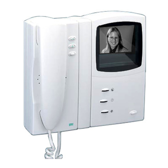
VH30ANC 'NoCoax' Video
Monitor Station (shown)
APPLICATION
The VH30ANC series 'NoCoax' video-intercom system
allows any number of VH30ANC series inside
monitor+handset stations to communicate with a single
door entry station with (or without) a built-in B&W
camera. When used as an apartment video-intercom
system, the VH30ANC can view the caller, speak with
the caller, and activate an electric door release (if re-
quired).
PROCEDURE
1. Read installation instructions for each unit to deter-
mine equipment location and installation method.
2. Install housings and wiring.
3. Install equipment.
4. Check wiring and connect. Observe all local
and national electrical and building codes.
5. Apply power and check system operation.
Copyright© 2003-2006, Alpha Communications®, All Rights Reserved.
VH30ANC Series (B&W Apartment Type)
'NoCoax' Video-Intercom Installation
and Use Instructions, used with the
VCU309 System Power Supply Unit(s)
HOUSING INSTALLATION AND
EQUIPMENT LOCATION
INSIDE MONITOR+HANDSET STATION(s)
Locate stations where needed at convenient speaking and
viewing height, about 4.5 feet (137 cm) from the finished
floor. Unit can be secured directly to the finished wall
surface or can be mounted over a single gang electrical
'gem' box or single gang electrical plaster ring.
DOOR ENTRY STATION
Locate the door entry station at a convenient speaking
location at the building entry location. NOTE: For best
picture (video) quality DO NOT POINT CAMERA
INTO DIRECT SUNLIGHT!!!
SYSTEM TRANSFORMER(s)
The T2440 24VAC system transformer(s) may be plugged
into an accessible source of 117 VAC, preferably within 50'
(15 meters) of the VCU309 system power supply unit(s),
but no closer than 3 feet (1 meter).
ELECTRIC DOOR OPENER (OPTIONAL)
The DO-001A (or equivalent 12-16VAC type) electric door
release is installed in the door jamb in place of the regular
door strike plate. It can be electrically operated by the
VH30ANC video monitor+handset station(s).
WIRING
INSIDE MONITOR+HANDSET STATION(s)
Run 4 conductor #22AWG (common) and 1 conductor
#22AWG (selective) cable from video monitor+handset to
video monitor+handset to the central equipment location
(where the VCU309 unit is found). Additional cables may
be used to serve other monitors on other risers (lines).
Cables may be straight or twisted pair type and may be
solid or stranded conductors. Depending upon additional
system options and/or functions you may need to run
additional wires. Please consult the factory for more
information. As with all systems, we recommend running
some spare wires, for future use.
Route cable (and all central equipment) away from AC
power wiring, transformers, fluorescent lights, light dim-
mers or other electrical devices. Protect cable from
damage. Shielded cable should be used if AC interference
is a concern, or if cables cannot be run adequately spaced
away from any source of electrical interference.
AWD086
Rev. 7 (11/2006)
Advertisement

Subscribe to Our Youtube Channel
Related Manuals for Alpha VH30ANC Series


Summary of Contents for Alpha VH30ANC Series
- Page 1 APPLICATION WIRING The VH30ANC series 'NoCoax' video-intercom system INSIDE MONITOR+HANDSET STATION(s) allows any number of VH30ANC series inside Run 4 conductor #22AWG (common) and 1 conductor monitor+handset stations to communicate with a single #22AWG (selective) cable from video monitor+handset to door entry station with (or without) a built-in B&W...
-
Page 2: Troubleshooting
DOOR RELEASE OPERATING INSTRUCTIONS Run 2 cond. #18 from the door release location to the TO PLACE A CALL TO THE REMOTE NH209TTA speaker/microphone assembly. Route away MONITOR+HANDSET UNITS: from any station wiring. Note: if wire run is longer than 50 feet At the remote door entrance station, depress button (for a (15m), use #16AWG cable. - Page 3 4. NO VOICE ON SYSTEM: Check volume control VH30ANC 'NOCOAX' TYPE MONITOR potentiometer(s) on NH209TTA speaker/microphone COMPONENT LISTING (in both directions; up and down). Check speaker/ microphone connections at entry station. Connect a single handset to system wiring only, to test voice operation.
- Page 4 General Monitor Mounting and Wiring Information Note: The internal PC/Component board and other internal components shown on this illustration is not the same as the VH309B board used in the VH30ANC 'NoCoax' type video- intercom monitor+handset. It is being shown for illustrative purposes only. Thank you.
- Page 5 TYPICAL WIRING DIAGRAM FOR SINGLE ENTRANCE SYSTEM WITH S.T.R.™ STYLE CAMERA AND ONE (1) VIDEO RISER (NO VBV-4 VIDEO DATA DISTRIBUTORS) NOTE: Install the KBS-1 video to data converter as close to camera as pos- sible. NOTE: Each KBS-1 must be powered by a separate NGC20 power supply NOTE: Each VBV-4 must...
- Page 6 TYPICAL WIRING DIAGRAM FOR SINGLE ENTRANCE SYSTEM WITH S.T.R.™ STYLE CAMERA AND MULTIPLE VIDEO DATA RISERS USING A SINGLE VBV-4 VIDEO DATA DISTRIBUTOR UNIT NOTE: Install the KBS-1 video to data converter as close to camera as possible. NOTE: Each KBS-1 must be powered by a separate NGC20 power supply NOTE: Each VBV-4 must be powered by a separate NG20 power supply...
- Page 7 TYPICAL WIRING DIAGRAM FOR DZ209 DIODE BOARD WHEN USED WITH THE VCU309 POWER SUPPLY AND VH30ANC 'NOCOAX' VIDEO-INTERCOM MONITOR(S) MODEL DZ209/5 (SHOWN) To additional lobby/entry call buttons lobby/entry call buttons Connect these terminals to the selective handset terminal 'II' on each video monitor handset To terminal To terminal...
- Page 8 USE ONLY THE SUPPLIED POWER SUPPLY! POWER SUPPLY IS FOR INDOOR USE ONLY. DO NOT REMOVE THE SERIAL NO. STICKER, AS THIS WILL VOID THE WARRANTY. ALPHA COMMUNICATIONS® • 42 Central Drive • Farmingdale NY 11735-1202 TOLL-FREE TECHNICAL LINE 1-800-666-4800 • Phone: 631-777-5500 • Fax: 631-777-5599...
Need help?
Do you have a question about the VH30ANC Series and is the answer not in the manual?
Questions and answers