
Related Manuals for Aros Flexus FM Series


Summary of Contents for Aros Flexus FM Series
- Page 1 THE SCIENCE OF CONTINUITY E T R I E B S H A N D B U C H A N U E L A N U A L...
- Page 2 NTRODUCTION Thank you for choosing this product. Our company is specialized in the design, development and production of uninterruptible power supplies (UPS). The UPS described in this manual is a high-quality, meticulously-designed product, built to guarantee the best performance. This manual contains detailed instructions on how to use and install the product. For information on how to use your equipment to its full potential, this manual should be kept close at hand beside the UPS and READ BEFORE STARTING TO WORK ON IT.
-
Page 3: Table Of Contents
ONTENTS OVERVIEW LEXUS RONT IEWS OF THE UPS C IEW OF THE ONNECTIONS IEW OF THE IEW OF THE ONTROL ANEL ATTERY OPTIONAL EPARATE YPASS NPUT OPTIONAL DDITIONAL NTERNAL ATTERY HARGERS OPTIONAL INSTALLATION TORAGE OF THE AND THE ATTERY REPARATION FOR INSTALLATION RELIMINARY INFORMATION LECTROMAGNETIC OMPATIBILITY... - Page 4 XTERNAL EMPERATURE ROBE ESCRIPTION RELIMINARY PERATIONS OWERING ON FOR THE IRST OWERING ON FROM THE AINS OWERING ON FROM THE ATTERY OWERING OFF THE RAPHIC ISPLAY ISPLAY ENUS PERATING ODES (SWMB) AINTENANCE YPASS EDUNDANT UXILIARY OWER UPPLY FOR UTOMATIC YPASS ROGRAMMABLE UXILIARY OCKET...
-
Page 5: Overview
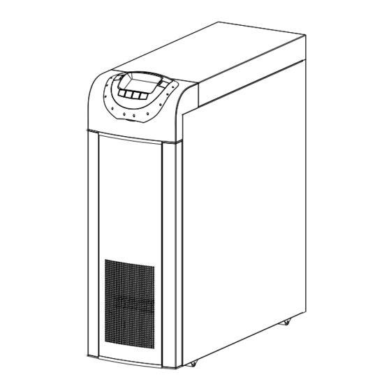
Thanks to its new, modern design, the use of a large graphic display, and above all the extra power provided by the battery charger (up to 6A recharge), the Flexus FM series represents a new reference standard for single-phase output UPS systems. -
Page 6: Front Views Of The Ups
RONT IEWS OF THE From left: Battery fuse holder isolator / Manual bypass Control panel with graphic display switch / Battery start button (COLD START) / 1/0 main power switch From left: Front door (to open the door, press and release Input switch / Separate bypass switch (optional) / the area marked Output switch... -
Page 7: View Of The Ups Connections
UPS C IEW OF THE ONNECTIONS Power connections: BATTERY, INPUT, SEPARATE BYPASS (optional), OUTPUT Connection for remote maintenance bypass command Connection for external Battery Box temperature probe Connection for external synchronization signal Connection for R.E.P.O. (Remote Emergency Power Off) command Area for the single-phase short-circuit bar Slot for power relay board - 58 -... -
Page 8: Rear View Of The Ups
IEW OF THE Slots for accessory communication cards RS232 communication port Powershare sockets USB communication port (max. total 10A on two sockets) Powershare socket thermal protector Ventilation fans (manual reset) Contact holder for AS400 Area for the parallel board (optional) - 59 -... -
Page 9: View Of The Control Panel
IEW OF THE ONTROL ANEL Mains power LED Battery low LED Battery power LED ECO mode LED Load on bypass LED Graphic display Stand-by / alarm LED F1, F2, F3, F4 = FUNCTION KEYS. The function of each key is indicated at the bottom of the display and varies according to the menu used. -
Page 10: Battery Box ( Optional )
ATTERY OPTIONAL THE BATTERY BOX IS AN OPTIONAL ACCESSORY PROVIDED FOR THIS RANGE OF UPS (SAME SIZE AND AESTHETIC DESIGN). The Battery Box contains batteries that increase the operating time of the UPS during prolonged black-outs. The number of batteries contained in it will vary according to the type of UPS to which the Battery Box is to be installed. The utmost attention must be paid to ensure that the battery voltage of the Battery Box corresponds to that supported by the UPS. -
Page 11: Input ( Optional )
EPARATE YPASS NPUT OPTIONAL DI” THE “ (OPTIONAL) VERSION OF THE UPS SERIES HAS SEPARATE BYPASS AND INPUT LINES. The UPS series with separate Bypass ensures a separate connection between the input and bypass lines. The UPS output is synchronised with the bypass line so as to safeguard against incorrect voltage changeovers in the alternate phases, in the event of automatic bypass or closing of the maintenance switch (SWMB). -
Page 12: Installation
INSTALLATION ALL THE OPERATIONS DESCRIBED IN THIS SECTION MUST BE CARRIED OUT EXCLUSIVELY BY QUALIFIED STAFF. The Company may no be held liable for any damage caused by incorrect connections or by operations that are not described in this manual. TORAGE OF THE AND THE ATTERY... -
Page 13: Electromagnetic Compatibility
LECTROMAGNETIC OMPATIBILITY This Uninterruptible Power Supply (UPS) conforms to the class C2 specifications (in accordance with the provisions laid down by the EN62040-2 standard: UPS - EMC requirement). In the home environment, it may cause radio interference. The user may have to take supplementary measures. This product is designed for professional use in industrial and commercial environments. -
Page 14: Removing The Ups And The Battery Box From The Pallet
EMOVING THE AND THE ATTERY OX FROM THE ALLET Cut the straps and remove the cardboard box by sliding it upwards Remove the accessory box and side blocks. NOTE 1: You will find the accessory box either inside the door of the UPS or on top of the UPS. -
Page 15: Preliminary
RELIMINARY HECK OF ONTENTS Having opened the package, start by checking the contents. BATTERY BOX (optional) Metal slides, Guarantee document, User manual, Metal slides, Guarantee document, Cable for connecting Cd-rom containing the UPS management software, the Battery Box to the UPS, 4 battery fuses (to be Serial connecting cable, 4 battery fuses (to be inserted in the "SWBATT"... -
Page 16: Electrical Connections
LECTRICAL ONNECTIONS WARNING: a 4-wire three-phase distribution system is required for the three-phase input connection. The standard version of the UPS must be connected to a TT, TN or IT type 3-phase power line + neutral + protective earth (PE), in compliance with the IEC 60364-3 specification; therefore phase rotation must be respected. - Page 17 UPS without any variation in neutral condition and with separate bypass input UPS with galvanic isolation and with separate bypass input UPS with galvanic isolation at output and separate bypass input - 68 -...
- Page 18 Separate bypass: if the separate bypass option is present, protective devices must be present on both the main power supply line and the bypass line. Note: the neutral of the input line and that of the bypass are commoned inside the equipment, so they must refer to the same potential.
-
Page 19: Protections Inside The Ups
ROTECTIONS INSIDE THE The following table shows the sizes of the disconnecting switches on the UPS system as well as the sizes of the battery fuses (SWBATT); these devices can be accessed from the front of the UPS. The table also provides details on the internal fuses (not accessible) used to protect the input and output lines, and the maximum input and nominal output currents. -
Page 20: External Protection Devices
XTERNAL PROTECTION DEVICES MAGNETOTHERMAL SWITCH As outlined above, the UPS has devices to protect against faults on the output and internal faults. magneto-thermal switch To set up the power line install a upstream of the UPS with intervention curve C in compliance with the EN 60947 specification, following the indications given in the following table: Automatic external protections Mains input... -
Page 21: Cable Sizes
ABLE SIZES The manufacturer recommends that the INPUT/OUTPUT and BATTERY cables pass under the UPS unit. Please refer to the following table for the minimum cross-sections to be used for the input and output cables. Cable sizes (mm INPUT mains / OUTPUT BATTERY** (optional) separate bypass (optional) -
Page 22: Connections For The Model With Separate Bypass
ONNECTIONS FOR THE MODEL WITH SEPARATE BYPASS The very first connection must be the protection conductor or the earth cable which should be inserted in the terminal marked PE. The UPS must be earthed before use. Connect the input and output cables to the terminal board as shown in the figure below: THE INPUT AND BYPASS NEUTRAL MUST ALWAYS BE CONNECTED. -
Page 23: Remote Emergency Power Off )
R.E.P.O. (R EMOTE MERGENCY OWER This isolated input is used to turn off the UPS remotely in case of emergency. The UPS is supplied from the factory with the “Remote Emergency Power Off” (R.E.P.O.) terminals short-circuited (see "View of the UPS connections"). If it is to be installed, remove the short-circuit and connect to the normally closed contact of the stop device using a cable that provides a double isolation connection. -
Page 24: Connection Of The Remote Maintenance Bypass
ONNECTION OF THE REMOTE MAINTENANCE BYPASS An additional maintenance bypass can be installed on a peripheral electric control panel, for example to replace the UPS without interrupting power to the load. It is essential to connect the SERVICE BYPASS terminal (see "View of UPS connections", point 2) to the auxiliary contact of the SERVICE BYPASS switch. - Page 25 DIAGRAM SHOWING REMOTE INSTALLATION OF THE MAINTENANCE BYPASS ON THE THREE PHASE – SINGLE PHASE MODEL WITH SEPARATE BYPASS Peripheral electric control panel UPS internal connections magneto-thermal switch compliant with the indications given in the “External Protection LINE switch: Devices” section. magneto-thermal switch NOTE: For installation with single phase input, use a bi-polar INPUT switch: switch compliant with the indications given in the “UPS Internal Protections”...
-
Page 26: Connecting The Battery Box To The Ups
ONNECTING THE ATTERY OX TO THE THE CONNECTION BETWEEN THE UPS AND THE BATTERY BOX MUST BE MADE WITH THE DEVICES POWERED OFF AND UNPLUGGED FROM THE MAINS UPS POWER-OFF PROCEDURE: Turn off all devices connected to the UPS or use the remote bypass option (if installed). Turn off the UPS following the relevant power-off procedure (see the “USE”... -
Page 27: Multiple Expansions
ULTIPLE XPANSIONS Several Battery Boxes can be connected in a cascade to ensure prolonged autonomy. The connections should be made as shown here below: WARNING (only for single UPS): No more than one UPS may be connected to each Battery Box or to more than one Battery Box connected in a cascade. -
Page 28: Use
ESCRIPTION The purpose of a UPS is to ensure a perfect power supply voltage for the devices connected to it irrespective of whether mains power is present or not. Once connected and powered, the UPS generates a sinusoidal alternating voltage with a stable amplitude and frequency, irrespective of the changes and/or variations occurring on the electricity network. -
Page 29: Preliminary Operations
RELIMINARY PERATIONS Visual check of the connection Check that all the connections have been made strictly following the indications given in the "Connections" paragraph. Check that the "1/0" button is in its "0" position (see "Front Views of the UPS" point 5). Check that all the isolators are open. -
Page 30: Powering On For The First Time
OWERING ON FOR THE IRST Set the "1/0" button to "1" and wait for a few seconds. Check that the display is turned on and the UPS enters "STAND-BY" mode. Check that no error messages appear indicating that the input cables do not respect the correct cyclic phase sense (for three-phase input only). -
Page 31: Powering On From The Mains
OWERING ON FROM THE AINS Set the “1/0” switch behind the door of the UPS in its “1” position. After a few moments, the UPS is turned on, the capacitors are precharged and the "Lock / stand-by" LED blinks: The UPS is in stand-by mode. -
Page 32: Graphic Display
RAPHIC ISPLAY At the centre of the control panel there is a large graphic display, which provides, in the foreground and in real time, a detailed overview of the current status of the UPS. Directly from the control panel you can turn the UPS on/off, view the electrical values of the mains, output, battery, etc., and make the main machine settings. -
Page 33: Display Menus
ISPLAY ENUS - 84 -... -
Page 34: Operating Modes
PERATING ODES The mode that guarantees maximum protection for the load is ON LINE mode, in which the energy for the load is converted twice and is generated perfectly sinusoidal at the output with the frequency and voltage set by the fine digital control of the DSP irrespective of the input (V.F.I.). -
Page 35: Programmable
EDUNDANT UXILIARY OWER UPPLY FOR UTOMATIC YPASS The UPS is equipped with a redundant auxiliary power supply that enables the UPS to run on an automatic bypass even when a failure occurs in the main auxiliary power supply. If a fault occurs in the UPS shutting off the main auxiliary power supply, the load is powered by the automatic bypass. -
Page 36: Onfiguring The Ups
ONFIGURING THE The table below illustrates all the possible settings at your disposal to tailor the UPS to best satisfy your needs. (Control Panel) = Indicates that the configuration can be changed not only from the configuration software but also from the control panel. Indicates that the configuration may only be changed from the configuration software. - Page 37 FUNCTION DESCRIPTION DEFAULT POSSIBLE SETTINGS MOD. Advanced Functions Selects the allowed • ± 0.25% input frequency range • ± 0.5% Input frequency for the switch to bypass ± 5% • ± 0.75% tolerance and synchronization of • ± 1 ÷ ±10 in steps of 1% the output Selects the voltage Low:...
-
Page 38: Communication Ports
OMMUNICATION ORTS The rear panel of the UPS (see Rear View of the UPS) contains the following communication ports: Serial port available with RS232 connector and USB connector. NOTE: the use of one connector automatically excludes the other. Expansion slots for additional COMMUNICATION SLOT interface boards On the front, covered by the terminal-cover, there is another expansion slot for the power relay board (optional 250Vac, 3A, 4 programmable contacts) RS232... -
Page 39: As400 Port
AS400 P AS400 PORT PIN # NAME TYPE FUNCTION POWER Isolated auxiliary power supply, +15V±5% 80mA max Ground to which the isolated auxiliary power supply (15V) POWER and the remote commands (Remote ON, Remote BYPASS, Remote OFF) refer When pin 2 is connected to pin 15 for at least 3 seconds, the REMOTE ON INPUT #1 UPS is turned on... -
Page 40: Buzzer
UZZER The status and faults of the UPS are signalled by the buzzer, which will emit a sound modulated according to the operating conditions of the UPS. The various kinds of sound are described here below: Sound A: The signal is emitted when the UPS is turned on or off using the relevant buttons. A single beep confirms power-on, activation of the battery test, cancellation of the programmed power-off. -
Page 41: Software
OFTWARE ONITORING AND ONTROL OFTWARE The monitoring software ensures an effective and user-friendly management of the UPS, displaying all the most important items of information such as the input voltage, load applied and battery capacity. It can also automatically perform shutdown operations, send e-mails, sms and network messages when specific user- selected events occur. -
Page 42: Troubleshooting Guide
TROUBLESHOOTING GUIDE The irregular operation of the UPS is very often not due to a malfunction, but to simple problems, inconveniences or distractions. Users are advised to consult the following table which provides useful information on how to solve some of the most common problems. - Page 43 PROBLEM POSSIBLE CAUSE SOLUTION JUMPER MISSING ON THE R.E.P.O. CONNECTOR (J13, THE DISPLAY SHOWS Mount the jumper or check that it is inserted correctly. POINT 5 - “VIEW OF UPS CONNECTIONS”) OR IS NOT INSERTED CORRECTLY SWMB MAINTENANCE Open the SWMB switch located behind the door. BYPASS SWITCH IS CLOSED THE DISPLAY SHOWS JUMPER MISSING ON THE...
- Page 44 PROBLEM POSSIBLE CAUSE SOLUTION OPEN THE PROTECTION Restore the upstream protection UPSTREAM OF THE BYPASS WARNING: check that there is no overload or short (ONLY FOR SEPARATE THE DISPLAY SHOWS circuit on the UPS output. BYPASS) ONE OR MORE OF THE FOLLOWING CODES: BYPASS SWITCH SWBYP Close the switch located behind the door.
- Page 45 PROBLEM POSSIBLE CAUSE SOLUTION THE DISPLAY SHOWS It is advisable to replace the UPS batteries, as they are ONE OR MORE OF THE no longer able to provide adequate backup power to the FOLLOWING CODES: THE BATTERIES DID NOT load. PASS THE PERIODIC A39, A40 EFFICIENCY CHECK...
-
Page 46: Status / Alarm Codes
TATUS ALARM ODES Using a sophisticated self-diagnostic system, the UPS can check and indicate on the display panel its status and any errors and/or faults that have occurred during its operation. When a problem arises, the UPS signals the event by showing the code and corresponding type of alarm on the display. - Page 47 Anomaly: “minor” problems that do not bring the UPS to a halt but affect its performance or inhibit the use of some of its functions. CODE DESCRIPTION Inverter Desynchronized External synchronism failed Overvoltage on input line 1 Overvoltage on input line 2 Overvoltage on input line 3 Undervoltage on input line 1 Undervoltage on input line 2...
- Page 48 Fault: more critical problems than “Anomalies” in that, if they persist, they may bring the UPS to a halt. CODE DESCRIPTION Internal communication error Incorrect input phase direction. Input fuse 1 broken or input relay blocked (will not close) Input fuse 2 broken or input relay blocked (will not close) Input fuse 3 broken or input relay blocked (will not close) Input relay 1 blocked (always closed) Input relay 2 blocked (always closed)
- Page 49 Lock: indicates that the UPS is locked, a lock is normally preceded by an alarm signal and, due to their gravity, causes the inverter to be turned off and the load to be powered via the bypass line (this procedure is excluded for locks caused by serious and persistent overloads and for a lock caused by a short circuit).
-
Page 50: Technical Specifications
TECHNICAL SPECIFICATIONS UPS Models 10 kVA 12 kVA 15 kVA 20 kVA Input Nominal voltage 380-400-415 Vac 3-phase with neutral (4 wire) / 220-230-240 Vac single phase Nominal frequency 50-60Hz Accepted input voltage tolerance due to no ±20% @ 100% load intervention of the battery (referred to 400Vac) -40% +20% @50% load ±20%... - Page 51 UPS Models 10 kVA 12 kVA 15 kVA 20 kVA Dimensions and weight Width x Depth x Height 320 x 840 x 930 mm Tower enclosure with wheels for transit, display inset in upper front section. Door Type of metal frame in lower front section giving access to switches and connections Weight (without batteries) 80Kg...
Need help?
Do you have a question about the Flexus FM Series and is the answer not in the manual?
Questions and answers