
Related Manuals for Aros Spring 500-3000VA


Summary of Contents for Aros Spring 500-3000VA
- Page 1 UNINTERRUPTIBLE POWER SUPPLY LINE-INTERACTIVE 500-3000VA (BATTERY BOX) - Manuale d’uso - - User’s manual - - Bedienungsanleitung -...
- Page 3 Questa parte del manuale contiene precauzioni da seguire scrupolosamente in quanto riguardano la SICUREZZA. Installazione Connettere l’UPS solo a prese con protezione di terra collegata. La presa protetta utilizzata per il collegamento deve essere facilmente accessibile e vicino all’UPS. Per il collegamento dell’UPS alla rete elettrica utilizzare solamente cavi di alimentazione testati VDE e marchiati CE.
- Page 4 SAFETY This part of the manual contains precautions that must absolutely be followed as they relate to SAFETY. Installation Connect the UPS system only to an earthed shockproof socket outlet. The building wiring socket outlet (shockproof socket outlet) must be easily accessible and close to the UPS system.
- Page 5 Dieser Teil des Handbuchs enthält sorgfältig zu befolgende Vorsichtsmassnahmen, da sie sich auf die SICHERHEIT beziehen. Installation Die USV nur an eine geerdete, stromschlagsichere Steckdose anschließen. Der Netzanschluss (stromschlagsichere Steckdose) muss leicht zugänglich und in der Nähe des USV Systems sein. Nur VDE getestete Netzkabel mit CE Siegel (z.B.
- Page 6 Cette partie du Manuel concerne les mesures de SÉCURITÉ à suivre scrupuleusement. Installation Raccorder l’ASI exclusivement à des prises à ayant une protection de terre branchée. La prise protégée utilisée pour le branchement doit être facilement accessible et située à proximité de l’ASI.
- Page 7 Esta parte del manual contiene las precauciones a seguir cuidadosamente en lo que se refiere a la SEGURIDAD. Instalación Conectar el SAI únicamente a enchufes con protección de toma de tierra. El enchufe protegido utilizado para la conexión debe ser de fácil acceso y encontrarse cerca del SAI. Para la conexión del SAI a la red eléctrica utilizar únicamente cables de alimentación ensayados VED y con marca CE.
- Page 8 Den här delen av handboken innehåller försiktighetsåtgärder som ska följas noggrant eftersom de har att göra med SÄKERHETEN. Installation Anslut UPS-enheten (oavbrytbar strömförsörjning) endast till ett jordat standardvägguttag. Vägguttaget (standardvägguttag) måste vara lättillgängligt och nära UPS-enheten. Använd endast VDE-testade, CE-godkända sladdar (t e datorns sladd) för att ansluta UPS-enheten till vägguttaget (standardvägguttag).
- Page 9 Dit gedeelte van de handleiding bevat de VEILIGHEIDSVOORSCHRIFTEN die strikt opgevolgd dienen te worden. Installatie Steek de stekker van het UPS systeem in een geaard schokbestendig stopcontact. Het stopcontact van de hoofdleiding (schokbestendig stopcontact) moet gemakkelijk toegankelijk zijn en zich in de buurt van het UPS systeem bevinden. Gebruik uitsluitend VDE-geteste, CE-gemarkeerde kabels (bijv.
- Page 10 Esta parte do manual contém precauções que devem ser seguidas rigorosamente, pois respeitam à SEGURANÇA. Instalação Somente conecte o sistema de alimentação ininterrupta (UPS) a uma tomada eléctrica anti choque com ligação terra. A caixa da cablagem de edifício com a saída da tomada eléctrica anti choque deve estar em lugar de fácil acesso e bem próxima ao UPS.
-
Page 11: Table Of Contents
COMMUNICATION PORT RS232 PORT USB P OMMUNICATION SOFTWARE ONITORING AND CONTROL SOFTWARE ONFIGURATION OFTWARE TROUBLE SHOOTING BATTERY REPLACEMENT PRING PRING PRING SPECIFICATION... - Page 12 Thanks you for choosing our product. Our manufacturer are renowned specialists in the development and production of uninterruptible power supplies (UPS). The UPS in this range are high quality products, designed and built with care in order to give you the best performance.
-
Page 13: Communication Port
This manual describes a uninterruptible power supplies (UPS) self-contained family of Spring (T, R, RT models) and the associated Battery box It is a line-interactive UPS topology. The UPS provides all connected equipment with secure protection against: a) black-outs (mains power off ) b) impulse-type mains overloads (input surge) c) mains voltage fluctuations The UPS unit automatically corrects small-scale mains fluctuations. -
Page 14: Front Views
Spring T Spring R Spring RT Nominal power [VA] 1100 1500 2000 1100 1500 2200 3000 Watts rating 1050 1350 1050 1540 2100 Output nominal [Vac] 200/208/220/230/240 voltage Dimensions 438X44X460 438X88X582 [mm] 110X235X383 160X235X425 LxHxD (19”x1Ux460) (19”x2Ux582) FRONT VIEWS Spring 500/800/1100 T Spring 1500/2000 T Spring 500/800/1100 R Spring 1500/2200/3000 RT... - Page 15 REAR VIEW Spring 500/800/1100 T Spring 1500/2000 T Spring 500/800/1100 R Spring 1500 RT...
-
Page 16: Usb Port
Spring 2200/3000 RT Spring Battery Box 1. RS232 serial communication port 2. Cooling fans 3. Telephone/modem protection 4. Input Breaker 5. IEC mains input plug 6. IEC output sockets (max 10A) 7. Communication expansion slot 8. Battery expansion connector 9. IEC 16A output socket 10. -
Page 17: Software
PENING THE PACKAGING AND CHECKING THE CONTENTS The first thing to do after opening the packaging is to check the contents The packaging should contain the following: USB cable Tower stands(Only for RT models) + slide IEC 16A Power cord(Only for 2200/3000 RT) assemblies (optional for RT models) User’s manual + CD-ROM software + Warranty IEC 10A connection cables... - Page 18 NSPECTING THE QUIPMENT Inspect the UPS upon receipt. If the UPS has been damaged during shipment, keep the box and packing material for the carrier. Notify the carrier and dealer immediately. LACEME MENT This UPS should be installed indoors with adequate airflow and free of contamination. Locate it in a clean and indoor environment, free from moisture, flammable liquids, and direct sunlight.
- Page 19 PRING MODELS AND BATTERY BOX 1. Put the bracketes and the bracket extension together 2. Slide down the UPS and the battery box vertically and put two UPS stands at the end of the tower. 3. Place the UPS and battery box into two stands carefully.
- Page 20 MODELS DISPLAY COVER SETUP The LCD display of the RT models can be rotate to adapt to rack or tower installation Follow the below steps and charts, you can rotate the LCD display: A. Rack To Tower B. Tower To Rack 1.
- Page 21 R-RT MODELS RACK SETUP Spring R and Spring RT can be installed in 19” racks. Use the following procedure to install UPS in a rack. 1. Align the mounting ears (optional for RT models) with screw holes on the side of the UPS. 2.
- Page 22 ONNECTION ONNECTION Connect the input of UPS with the mains power. Connect loads to to the sockets on the rear of the UPS with the IEC-IEC cables or a cable with maximum length of 10 meters. Notice: do not connect any loads that absorb more than 10A to the 10A IEC sockets. These loads should be connected exclusively to the 16A IEC socket when this is available.
- Page 23 DDITIONAL BATTERY BOX INSTALLATION Spring 2200 RT and 3000 RT models includes external battery port that allows to provide additional battery runtime. There is one external battery port for the UPS itself. Caution: Connecting battery cable to external battery port may occur sparkle if adding up additional battery.
- Page 24 To turn on/off the UPS, you should press the on/off switch three seconds at least. Only for the first time you switch on: after about 30 sec., check that the UPS is working correctly by: 1. Simulating a black-out by removing the mains power cable 2.
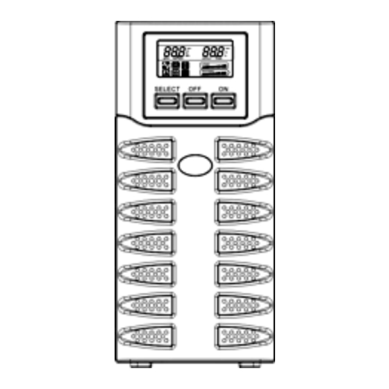
- Page 25 RONT ANEL There are three buttons on the front panel ,which have been marked with “ON”, “OFF”,and “SELECT”. CD TOTAL VIEW...
- Page 26 The detail description for the Part A(the left field of the LCD): INPUT-VAC : the input voltage(unit: Volt) INPUT-Hz: the input frequency(unit: Hz) BATTERY-V: the total voltage of the battery (unit: Volt) BATTERY-%: the estimated capacity of the battery in percentage BATTERY-MIN: the estimated battery remain time (unit: Minute) The detail description for the Part B(the right field of the LCD): OUTPUT-VAC: the output voltage(unit: Volt)
- Page 27 CD INDICATOR PANEL This chapter gives a detailed description of all indicator panel. ICON STATUS DESCRIPTION Steady Indicates a fault (see table 1) Flashing The UPS is in standby mode Steady The UPS is operating on mains power The UPS is operating in battery mode and will beep at regular Steady intervals.
- Page 28 Table 1: Fault List LCD Symbol In Description Solution Advice Part A The UPS is over- loaded Check load level display and remove some load 1. Ensure the ambient temperature is below 40°C The UPS is over temperature 2. Turn off the UPS and wait for a while to make it cooling 1.
- Page 29 DISPLAY DISPLAY CO CONFIGU NFIGURATION The LCD display has two fields, left(Part A) and right(Part B). Left filed can shows the following measures: “Input voltage”, “Input frequency”, “Battery voltage”, “Battery capacity percentage” and “Estimate battery runtime”. For right field the measures available are: “Output volage”, “Output frequency” and “Load percentage” Push the “SELECT”...
- Page 30 Step 3: Push the “ON” button (confirm the left field), and the characters “INPUT”, “VAC”and corresponding measure (the blank font) of the left field will blink. Step 4: Push the “SELECT” button, and the characters “INPUT”, “Hz” and corresponding measure (the blank font) of the left field will blink.
- Page 31 Step 7: Push the “SELECT” button, and at last the characters “BATTERY”, “MIN” and corresponding measure (the blank font) of the left field will blink. Step 8: Push the “ON” button (confirm this measure), then the measure of the left field is the “Estimate battery runtime”.
- Page 32 Step 11: Push the “SELECT” button, and the characters “OUTPUT”, “Hz” and corresponding measure (the blank font) of the right field will blink. Step 12: Push the “SELECT” button, and the characters “LOAD”, “%” and corresponding measure (the blank font) of the left field will blink. Step 13: Push the “ON”...
- Page 33 UZZER INDICATION When keeping “ON”, “SELECT” or “OFF” button pressed for 1 to 3 seconds buzzer will beep; If UPS is fault(because of over temperature or fan fail…) buzzer will beep steadily; If battery bad or over charged, buzzer will beep steadily for warning; If UPS is over load, buzzer will beep intermittently(1s on/1s off) for warning;...
- Page 34 RS232 PORT The RS232 serial port allows the connection of a PC (COM port) by means of a pin-to-pin serial cable provided (if a different cable is used, it should be of the pin-to-pin type with a max. length of 3 metres). The computer interface in factory setup port has the following characteristics as shown: RS232 CONNECTOR 3 4 5...
- Page 35 The CD-Rom provided includes two software programmes that allow the user to perform UPS monitoring, control and configuration operations. ONITORING AND AND CON CONTROL SOFTWARE The Watch & Save 3000 software ensures efficient and intuitive UPS management , by displaying all the most important information such as input voltage, applied load, battery capacity, etc.
-
Page 36: Trouble Shooting
Audible Alarm Trouble Shooting Problem Cause Solution Sounding every The UPS is on battery Check the input voltage 4 seconds Sounding every The battery is running low Save your work and turn off your equipment second Continuously The UPS fails Please contact your local dealer sounding Sounding every... -
Page 37: Battery Replacement
When the Bad Battery indicator lights and there is a continuous sounding, the battery may need to be replaced. Please check the battery connection or contact your local dealer to order new battery. CAUTION: A battery can present a risk of electrical shock and high short circuit current. The following precautions should be observed before replacing the batteries. - Page 38 PRING 1. Remove the UPS front panel by pulling on both ends. 2. Disconnect the battery cable from the UPS, then unscrew the battery bracket from the UPS 3. Remove the battery plate retaining battery stably. 4. Pull the battery out onto flat area 5.
- Page 39 PRING 1. Remove the UPS front panel by pulling on both ends. 2. Unscrew the battery bracket from the UPS. Remove the battery plate retaining battery stably. 3. Disconnect the battery cable from the UPS. 4. Pull the battery out onto flat area 5.
- Page 40 Spring T 1100 1500 2000 1100 1500 2000 NOMINAL POWER Watt 1050 1350 Nominal Voltage 230 VAC 160VAC ± 3% INPUT Mains voltage range 294VAC ± 3% Frequency Range 50/60Hz Autoselection Voltage Regulation (Batt. Mode) 230V +5% ,-10% Frequency 50/60Hz Autoselection OUTPUT Frequency Regulation (Batt.
- Page 41 Spring R Spring RT 1100 1500 2200 3000 1100 1500 2200 3000 NOMINAL POWER Watt 1050 1540 2100 Nominal Voltage 230 VAC 160VAC ± 3% INPUT Mains voltage range 294VAC ± 3% Frequency Range 50/60Hz Autoselection Voltage Regulation (Batt. 230V +5% ,-10% Mode) Frequency 50/60Hz Autoselection...
Need help?
Do you have a question about the Spring 500-3000VA and is the answer not in the manual?
Questions and answers