Table of Contents
Advertisement
Advertisement
Table of Contents

Related Manuals for Motostar ECLISTAR


Summary of Contents for Motostar ECLISTAR
- Page 1 SWING GATE OPERATOR ECLISTAR INSTALLATION MANUAL...
- Page 2 INDEX 1.0 General characteristics pag. 1.1 Components pag. 1.2 Technical features pag. 1.3 Dimensions pag. 1.4 Main component parts of a standard installation pag. 1.5 Limits to use pag. 2.0 Installing the gearmotor pag. 3.0 Control panel pag. 3.1 Assembling and fi xing the casing pag.
-
Page 3: Component Parts
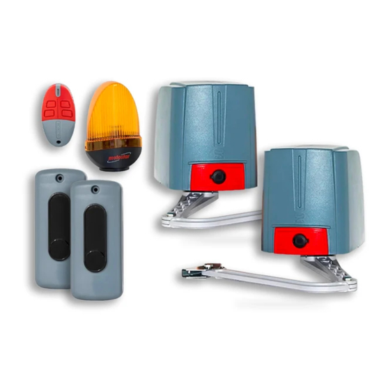
COMPONENT PARTS Control panel Fixing nuts and screws Gearmotor Transmission arms Base bracket Cable feedthroughs Head brackets Cable gland TECHNICAL CHARACTERISTICS 24V D.C. self-locking gearmotor, powered by a 230V A.C. control panel. Power supply to control panel: Max frequency of use: 45 cycles/h 230V A.C. - Page 4 MAIN COMPONENT PARTS OF A STANDARD INSTALLATION Flashing light with built-in antenna Keypad selector Control panel Photocell Junction box for passage of electrical cables Gearmotors Transmitters The standard installation shown is only an example. Check the illustrations and the contents list in the kit box you have purchased.
- Page 5 Ⓓ+Ⓕ Ⓓ+Ⓕ Ⓐ+Ⓑ+Ⓒ Ⓐ+Ⓑ+Ⓒ +Ⓓ+Ⓔ+Ⓕ +Ⓓ+Ⓔ+Ⓕ Ⓒ Ⓒ Ⓒ+Ⓔ Ⓒ+Ⓔ Ⓐ Ⓐ 119R7179GB 119R7179GB The data and information in this manual are subject to change at any time and without need of prior notice - ver. 07/2009 - Pag.
-
Page 6: Limits To Use
LIMITS TO USE The maximum width of the gate leaf must not exceed 2.2 metres and its max weight cannot exceed 300 kg. (mm) Opening angle 140÷205 0÷50 140÷195 75÷100 90° 140÷185 125÷150 140÷175 175÷200 180÷210 110° 200÷205... - Page 7 INSTALLING THE AUTOMATION GATE CHECKS BEFORE INSTALLING • Check that the gate structure is sturdy and that the hinges are in proper condition. • Make sure that there is a closing and opening mechanical door endstop (that is well secured to the ground) to prevent over-run of the gate leaf.
- Page 8 PRELIMINARY OPERATIONS AND BRACKET MOUNTING - Set up the tubes for the electrical connection and junction boxes. - Insert the electrical cables that come from the junction pit into the tubes, making sure the sections are right depending on the use to be made (see installation on page 4).
- Page 9 PRELIMINARY OPERATIONS AND BRACKET MOUNTING - Secure the base plate, using securing elements chosen according to the post type and materials. - Insert the cable feedthroughs and the cable gland into the base plate holes. - Position the head bracket onto the gate leaf at a “C”...
- Page 10 SECURING THE GEARMOTOR - Remove the cover, insert the gearmotor into the base bracket so that it corresponds to the 4 holes and secure it using the supplied screws and nuts. Warning: a sticker tag on the microswitch shows whether that gearmotor should be mounted to the right (DX) or to the left (SX).
- Page 11 SECURING THE GEARMOTOR - Secure the curved arm to the head bracket using the supplied screw and nut. Lubricate it and check that the arm rotates freely. - Perforate the cable feedthrough to the base bracket on the side of the cable gland.
- Page 12 ADJUSTING THE ENDSTOPS ADJUSTING THE LEFT HAND GEARMOTOR OPENING ENDSTOP INNER VIEW - With the motor released, place the gate leaf at a distance of 5 cm from the opening endstop. - Rotate the lower cam clockwise ..until the microswitch is activated. Upper Closing microswitch...
- Page 13 ADJUSTING THE ENDSTOPS ADJUSTING THE - Rotate the upper cam counter- CLOSING ENDSTOPS clockwise ..N.B. Always adjust the opening endstop before adjusting the closing one. Warning: the upper cam of the operator’s endstop assembly is set up for gate leaf ...
- Page 14 ADJUSTING THE ENDSTOPS continue > adjusting the left hand closing endstop - Release the gearmotor and completely close the gate leaf. N.B. If the gate leaf measures less than N.B. If the gate leaf measures less than 1.20 metres ... 1.20 metres ...
- Page 15 ADJUSTING THE ENDSTOPS ADJUSTING RIGHT HAND GEARMOTOR THE OPENING ENDSTOP INNER VIEW - With the motor released, place the gate leaf at a distance of 5 cm from the opening endstop. - Rotate the lower cam counter- clockwise ..until the switch of the micro is activated.
- Page 16 ADJUSTING THE ENDSTOPS ADJUSTING - Rotate the upper cam clockwise ..THE CLOSING ENDSTOP N.B. Always adjust the opening endstop before adjusting the closing one. Warning: the upper cam of the operator’s endstop assembly is set up for gate leaf ...
- Page 17 ADJUSTING THE ENDSTOPS continue > adjusts the right hand closing endstop - Release the gearmotor and completely close the gate leaf. N.B. If the gate leaf measure less than N.B. If the gate leaf measure less than 1.2 metres ... 1.2 metres ...
-
Page 18: Control Panel
CONTROL PANEL Il The control panel is made up of a two-colour ABS casing, featuring a fully opening hatch which can be hinged either right or left. Inside, the control board featuring a receiver radio card and transformer. We suggest installing it in an area protected from accidental impacts or possible tampering. - Page 19 LEGEND 1 - Transformer 14 - Terminals for connecting up gearmotors 2 - Card fuse 15 - Motor fuse 3 - Trimmer for adjusting automatic closing time 16 - Terminals for powering up accessories 4 - Terminals for connecting the transformer 17 - Terminals for connecting up warning signal accessories...
- Page 20 ASSEMBLING AND SECURING THE CASING Before securing the casing to the wall, you need to assemble and mount the hinges on the side you prefer. (N.B. you may also just wish to secure the cover using the 4 screws). Assemble the pressure hinges.
- Page 21 - Position and secure the base of the casing using securing elements suitable to the structure and surface to which you will be securing. - Insert the tubes and cable cable feedthrough glands (not supplied) under the base of the container, removing the existing cable feedthroughs.
- Page 22 CONTROL BOARD AND ITS FUNCTIONS – DESCRIPTION The control panel should be powered All the connections are protected by with 230V A.C., with max 50/60Hz fre- fast (F) fuses, see table on page 19. quency. The card provides and controls the fol- The command devices and accesso- lowing functions: ries are rated at 24V (N.B.
-
Page 23: Electrical Connections
ELECTRICAL CONNECTIONS GEARMOTORS, TRANSFORMER AND POWER SUPPLY Transformer OTOR DELAYED CLOSING HE GATE LEAF OPENS FIRST AND CLOSES SECOND OTOR DELAYED OPENING THE GATE LEAF OPENS SECOND AND CLOSES Power supply FIRST 230V (A.C.) 50/60z * to prevent any mechanical interference between the gate leaves... -
Page 24: Command Devices
COMMAND DEVICES N.C. contact for STOP buttons (remove the bridge wire). - Stops the gate while excluding the automatic closing cycle. To resume movement press the command or transmitter button. N.O. contact for Command button, for A) Opening and Closing the gate (see dip switch 2 for which mode) …... - Page 25 WARNING AND LIGHTING DEVICES Sock RG58 cable Warning light (24V – 3W): It stays on to signal that “gate is open”. - (24V – 25W) Flashing light: it activates during gate movement and pre-fl ashing mode can also be selected … - (24V-25W) cycle lamp: which stays on during the entire opening and closing cycles (Automatic Closing...
- Page 26 SAFETY DEVICES: PHOTOCELLS How to connect up a pair of photocells to obtain gate REOPENING, when they detect an obstacle during closing phase. Dip switch 7 must also be placed to OFF. REOPENING Transmitter Receiver How to connect up a pair of photocells (or a 2 pair) to obtain temporary gate STOP, when they detect an obstacle during movement.
-
Page 27: Function Selection
FUNCTION SELECTION Select the functions by positioning the dip SEQUENTIAL COMMAND switches to ON or OFF, using a screw driver 2 ON + 3 OFF as shown in the picture. By pressing the button connected on G-Ps or that on the transmitter, the command se- quence will be Open-Stop-Close-Stop. - Page 28 PRE-FLASHING REOPENING 4 ON 7 OFF The (Lumistar) fl ashing light connected on When detecting an obstacle during closing, 20-K1, fl ashes 5 seconds before allowing the photocells trigger the gate to reopen any opening or closing action. (see page 26). If there are no photocells or other safety devi- ces connected, leave the dip switches ON.
- Page 29 ADJUSTING FUNCTIONS To adjust the trimmers, use a small screw driver by turning it clockwise (+) to increase or counter-clockwise (-) to reduce. FA FC F FA FC F FC FC FA FA 230V 630mA 630mA FA FC F FA FC F FA FC F FA FC F FC FC...
- Page 30 CHECKING SETTINGS OF ENDSTOP ASSEMBLY Make sure you have secured the area in which you are working (i.e. loose cable ends or live wires, equipment that may interfere with the movement of the structures, unauthorised personnel or children), and then power up the system. Check endstop setting, which was made when gearmotor was installed (page 12 to 17), making sure whether the gate leaves reach the desired maximum opening point.
- Page 31 PROGRAMMING THE RADIO CODE … now, with a transmitter button send the If replacing the control board or the radio radio code: the LED will stay on to indicate card, you need to memorise the radio codes the code has been memorised. again, as explained below.
-
Page 32: Led Control Functions
LED CONTROL FUNCTIONS ALIM ALIM PROG PROG D1 D1 D3 D3 ST ST Yellow led When on, it signals that the total stop button is either activated or not working. Yellow led When on, it signals that the photocells in temporary stop mode are either activated or not working. -
Page 33: Warnings And Precautions
• Do not counter the force of the operator, as this swing gate within the limits and modes described in can lead to hazardous situations. this manual. Motostar cannot be held liable • Do not allow children to play or loiter for any damage cased from wrongful, within the operating range of the erroneous or unreasonable use. -
Page 34: Periodic Maintenance
MAINTENANCE PERIODIC MAINTENANCE The periodic maintenance action which you may carry out, that do not require any particular prescriptions, are: - visual inspections of the gate structure, especially of the hinges and opening and closing endstops; - inspection of the operator’s area of movement, removing any vegetation that may have grown impeding the photocells to work properly;... -
Page 35: Maintenance Logs
MAINTENANCE LOGS Periodic maintenance log: table for logging any actions performed by the user (see page 34); we suggest performing an inspection every six months. Date User’s_signature Date User’s_signature Notes Notes - _ _ _ _ _ _ _ _ _ _ _ _ _ _ _ - _ _ _ _ _ _ _ _ _ _ _ _ _ _ _ _ _ _ _ _ _ _ - _ _ _ _ _ _ _ _ _ _ _ _ _ _ _ - _ _ _ _ _ _ _ _ _ _ _ _ _ _ _ _ _ _ _ _ _ _ - _ _ _ _ _ _ _ _ _ _ _ _ _ _ _ _ _ _ _ _ _ _ _ _ _ _ _ _ _ _ _ _ _ _ _ _ _ - _ _ _ _ _ _ _ _ _ _ _ _ _ _ _ _ _ _ _ _ _ _ _ _ _ _ _ _ _ _ _ _ _ _ _ _ _... -
Page 36: Manufacturer's Statement
_ _ _ __ _ _ _ _ _ _ _ _ _ _ _ __ _ _ _ _ _ _ _ _ Declares that the products hereto _ _ _ _ _ _ _ _ __ _ _ _ _ _ _ _ _ _ _ _ __ _ _ _ ECLISTAR...
Need help?
Do you have a question about the ECLISTAR and is the answer not in the manual?
Questions and answers