
Related Manuals for Standard Horizon PF-P320

Summary of Contents for Standard Horizon PF-P320
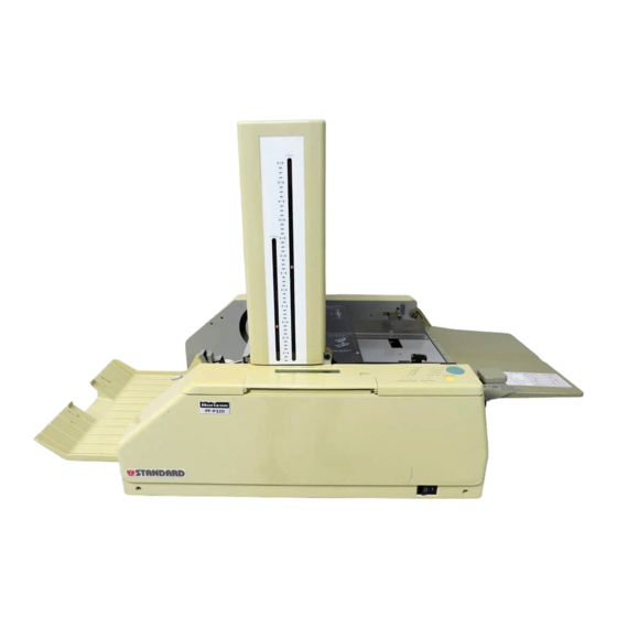
- Page 1 SERVICE MANUAL Standard Horizon PF-P320 Paper Folder Read this manual, and thoroughly familiarize yourself with its contents before operating or servicing this equipment. PF-P320/SM...
-
Page 2: Foreword
FOREWORD Paper Folder Model PF-P320 This manual is designed to help you to keep the machine in a good operating condition. Read, study and keep this manual in a safe and convenient place. Do not perform any maintenance until you read and understand the instructions in this manual. -
Page 3: Safety Instruction
Safety Instruction 1. Read and understand all safety instructions with a signal WARNING, CAUTION. If safety instructions are ignored, personal injury will result. 2. HORIZON INTERNATIONAL INC. cannot anticipate every possible situa- tion that might involve a potential hazard. The instruction in this manual are therefore not all inclusive. -
Page 4: I Necessary Tool For Maintenance And Repair
I Necessary Tool for Maintenance and Repair Use the following tools for maintenance and repair. Screw Driver No. 2 Screw Driver 6 to 7 mm Allen Wrenches 1.5, 2, 2.5, 3, 4, 5, and 6 mm Open-ended Wrench 5.5 x 7 mm 8 x 10 13 x 17 Box Wrench... -
Page 5: Table Of Contents
Contents FOREWORD .......................... I Safety Instruction ........................II I Necessary Tool for Maintenance and Repair ..............III II Signs and Abbreviations in This Manual ................III 1. Specifications and Functions ..................1 2. Operation Overview ......................2 3. Sheet Flow ........................4 4. -
Page 6: Specifications And Functions
1. Specifications and Functions A. Specifications Model PF-P320 Standard Sheet Size A5 (manual setting), A4, A3, B4, B5 (5.5" x 8.5", 8.5" x 11", 8.5" x 14", 10" x 14", 9" x 11", 11" x 17") Sheet Size Maximum : 311 x 432 mm (12.2" x 17") Minimum : 65 x 90 mm (2.6"... -
Page 7: Operation Overview
2. Operation Overview 1. Turn on power switch. Display Indication 1st and 2nd stoppers move to home position " Please wait" automatically. Then stoppers moves accord- ing to fold pattern and sheet size memorized "Set Delivery Roller" at previous operation. When feed tray lever rises at that time, motor, fold roller and "0 / 0"... - Page 8 2. Operation Overview 8. Mode select button in memory mode has four modes ; "XXX.X Set Stopper 1" - 1st stopper input mode "XXX.X Set Stopper 2" - 2nd stopper input mode "Memory 1 Press MEMORY" - Memory 1 memory mode "Memory 2 Press MEMORY"...
-
Page 9: Sheet Flow
3. Sheet Flow 2nd Buckle 1st Buckle 3rd Drive Roller Stopper 2nd Drive Roller 1st Drive Roller Feed Roller Deflector Delivery Belt Fold Roller 1. Feed roller feeds sheet to 1st drive roller. 2. Sheet is nipped between 1st drive roller and fold roller and then transported to 1st buckle. -
Page 10: How To Remove Covers
4. How to Remove Covers CAUTION - Turn off main power and remove any covers. Buckle Cover Tool : Screwdriver - Bind Screw M4 x 8 (4 pcs) Rear Cover - Bind Screw M4 x 8 (2 pcs) - Tapping Screw M4 x 10 (2 pcs) Front cover is installed with the top edge fitted with operation panel. -
Page 11: Troubleshooting
5. Troubleshooting A. PF-P320 Does Not Work with Start Button or Test Feed Button (Cause 1) (Remedy 1) Feed clutch solenoid is not Adjust the position of feed clutch solenoid so that the positioned properly. clearance between clutch lever and clutch stopper is 0.5 to 1 mm (0.02"... - Page 12 5. Troubleshooting B. Sheets Is Not Folded Correctly with Single Fold (Cause) (Remedy) Deflector is deformed or de- Adjust deflector so that the clearance between 2nd drive flector drive solenoid is not roller and deflector is 0.2 to 0.3 mm (0.008" to 0.02") positioned properly.
- Page 13 5. Troubleshooting D. Delivery Belts Do Not Work (Cause 1) (Remedy 1) Sheet slips on delivery belts a) Tension Adjustment because delivery belts are Loosen tension adjust screw and adjust tension of deliv- loosen. ery belts. b) Delivery Belts Replacement Remove bottom plate of delivery belts and then drive pulley shaft and slave shaft.
- Page 14 4 mm. NOTE - Adjust sensor within 2 mm. Otherwise PF-P320 may be locked by stopper's hitting upper limit stopper. Upper Limit Stopper - When stopper fix screw is fastened, make sure stopper is not skewed.
- Page 15 5. Troubleshooting G. Double Feed Occurs (Cause 1) Sheet is too thin. (Out of speci- fication) (Remedy 2) (Cause 2) Clean double feed stop pad or replace it with new one. Feed roller or double feed stope pad is worn out. (Remedy 3) (Cause 3) Fan sheets well.
- Page 16 5. Troubleshooting (Cause 2) (Remedy 2) Fold roller spring is loosen. Replace fold roller spring. NOTE - In case wire is cut, replace wire as shown in the draw- ing below. Lever Fold Roller Spring Wire Roller Lever (Remedy 3) (Cause 3) 1.
- Page 17 5. Troubleshooting (Cause 4) (Remedy 4) Fold rollers are dirty with ink. Clean fold rollers with alcohol soaked cloth. (Cause 5) (Remedy 5) Sheets are jammed in buckle. Remove all jammed sheets in buckles. (Cause 6) (Remedy 6) Support rollers are set improp- Readjust support roller position.
-
Page 18: Troubleshooting (Electronic Control)
5. Troubleshooting (Electronic Control) [1] "Error Check Breaker" Is Still Indicated in Spite of Turning Power on (Remedy 1) (Cause 1) Push breaker button below feed tray. (Refer to page 16.) Circuit breaker for buckle is tripped because of sheet jam. (Remedy 2) (Cause 2) Turn off power and lower stopper with stopper... - Page 19 Pattern and Sheet Size Do Not Illuminate Correctly (Cause) (Remedy) Press reset button to clear memory in CPU. If PF-P320 Memory in CPU may be broken. does not work properly still, replace control P.C.B.. [5] Buckle Stopper Lowers Further After It Stops at Bottom Dead End...
- Page 20 5. Troubleshooting (Electronic Control) [7] "0 / 0 Feed Error" Is Indicated on Monitor After 3 to 4 Sheets (Cause) (Remedy) Counter sensor unit may be Check that counter sensor works correctly with counter broken. sensor LED on control P.C.B.. And check sensor wires are cut or short-circuit.
-
Page 21: Message List
6. Message List "Error Check Breaker" This will be indicated when stopper does not return to home position in time after power switch is turned on. "Please wait." This will be indicated while stopper is moving when power is turned on. This will be indicated when feed tray is empty. -
Page 22: Sensor And Electronic Parts Descriptions
7. Sensor and Electronic Parts Descriptions 2nd Buckle Encoder Sensor (QPW-422) 1st Buckle Encoder Sensor (QPW-422) Count Sensor (Projector) 2nd Buckle Home Position Sensor Count Sensor (Receiver) 1st Buckle Home Position Sensor No Sheet Microswitch Buckle Open Sensor LED P.C.B. (QPW-307) Circuit Breakers for Buckle... -
Page 23: Led Descriptions And Dip Sw Set Up
8. LED Descriptions and DIP SW Set Up CON4 CON5 DSW1 PSEN CON2 CON1 1. 2nd Stopper Encoder Sensor A VR1 Slow Speed Adjustment VR 2. 2nd Stopper Encoder Sensor B VR3 LCD Brightness Adjustment VR 3. 2nd Stopper Home Position Sensor DSW1 4. -
Page 24: Drive Section Line Diagram
9. Drive Section Line Diagram (19) -
Page 25: Control Section Signal Line Diagram
10. Control Section Signal Line Diagram (20) -
Page 26: Buckle Section Line Diagram
11. Buckle Section Line Diagram (21) - Page 27 (22)
- Page 28 Standard Business Systems 10 Connector Road, Andover, MA 01810 PF-P320/SM (978) 470-1920 (978) 470-2771 Revision 3...
Need help?
Do you have a question about the PF-P320 and is the answer not in the manual?
Questions and answers