Table of Contents
Advertisement
Pub. 43004-010H
G A I - T R O N I C S ® C O R P O R A T I O N
A H U B B E L L C O M P A N Y
ITA2000A Series Tone Remote Adapter
with Scanning
User and Installation Manual
*U.S. Patent 6,950,653
GAI-Tronics Corporation 400 E. Wyomissing Ave. Mohnton, PA 19540 USA
610-777-1374 800-492-1212 Fax: 610-796-5954
V
.
-
.
ISIT WWW
GAI
TRONICS
COM FOR PRODUCT LITERATURE AND MANUALS
Advertisement
Table of Contents

Subscribe to Our Youtube Channel
Related Manuals for GAI-Tronics ITA2000A Series

Summary of Contents for GAI-Tronics ITA2000A Series
- Page 1 A H U B B E L L C O M P A N Y ITA2000A Series Tone Remote Adapter with Scanning User and Installation Manual *U.S. Patent 6,950,653 GAI-Tronics Corporation 400 E. Wyomissing Ave. Mohnton, PA 19540 USA 610-777-1374 800-492-1212 Fax: 610-796-5954 ISIT WWW TRONICS COM FOR PRODUCT LITERATURE AND MANUALS...
- Page 2 GAI-Tronics. WARRANTY GAI-Tronics warrants for a period of one (1) year from the date of shipment, that any GAI-Tronics equipment supplied hereunder shall be free of defects in material and workmanship, shall comply with the then-current product specifications and product literature, and if applicable, shall be fit for the purpose specified in the agreed-upon quotation or proposal document.
-
Page 3: Table Of Contents
Table of Contents FOREWORD ................................1 ..............................1 COPE OF ANUAL ................................ 1 OMENCLATURE ..........................1 RDERING EPLACEMENT ARTS ..............................1 ERVICE AND EPAIR FCC I ..........................1 NTERFERENCE ARNING CMOS I ..................2 ... - Page 4 Table of Contents ITA2000A Series Tone Remote Adapter ......................25 ADIO ELEPHONE ONNECTIONS Analog Facility Interface Codes ......................... 25 Telephone Line Connection Table ........................25 .................................. 26 UMPERS Jumper Table ..............................26 ) ....................27 ...
-
Page 5: Foreword
Installation section of this manual. Nomenclature The model number, located on the nameplate on the bottom, specifically identifies GAI-Tronics equipment. If additional options are ordered, the option will be identified on the circuit board. Many ITA2000A features are the same in both Conventional and Scan modes. If a feature is particular to either mode, the mode will be identified. -
Page 6: Safe Handling Of Cmos Integrated Circuit Devices
Foreword ITA2000A Series Tone Remote Adapter Safe Handling of CMOS Integrated Circuit Devices Many of the integrated circuit devices used in communications equipment are of the Complementary Metal Oxide Semiconductor (CMOS) type. Because of their high open circuit impedance, CMOS integrated circuits are vulnerable to damage from static charges. -
Page 7: Description
Description Features and Benefits of the ITA2000A Tone Remote Adapter Feature Benefit Adjustable receive input Allows flexibility with different radio systems and user sensitivity and transmit output environments, where radio output levels, line losses, and noise level factors vary. Autolevel Reduces the need for site visits to adjust audio pots. -
Page 8: Additional Features And Benefits Of The Ita2000A Tone Remote Adapter In Scan Mode
Description ITA2000A Series Tone Remote Adapter Additional Features and Benefits of the ITA2000A Tone Remote Adapter in Scan Mode Feature Benefit Adds scanning capability to Enhances radio functionality by using channel steering capability of conventional multi-channel both non-scanning and scanning radios. Reduces overall system cost. -
Page 9: Product Overview
Scan mode (using patented techniques), adds tone remote scanning and scan start/stop capability to conventional, multi-channel, steering-capable radios. Dispatch points are updated using these techniques through the use of the parallel status update feature found in the GAI-Tronics Model ITR2000A and IPE2500A Desk Sets. -
Page 10: Specifications
Description ITA2000A Series Tone Remote Adapter Specifications Color ..............................Black Physical size ....................7.03 W 6.3 L 1.5 H inches Weight ..............................4 lbs. Temperature range ......................... −30º C to 70º C Humidity ............................ 95% at 50º C Input power (main or aux.) .............. -
Page 11: Operation
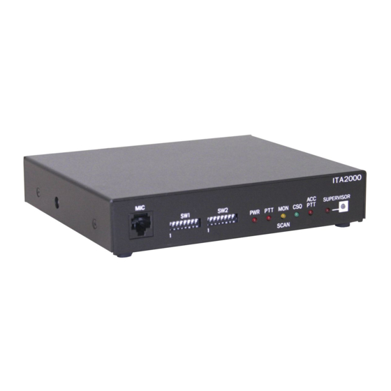
Operation Front Panel LED Operation ITA2000 Front View of the ITA2000A PWR LED The PWR LED illuminates to indicate that the ITA2000A power is on and the DSP is operating. PTT LED The push-to-talk LED, labeled PTT, illuminates when a valid transmit request has been decoded or the mic PTT is actuated. -
Page 12: Supervisor Button
An external microphone monitor function places the ITA2000A in the monitor mode while asserting PL/DPL disable at the radio connector. The microphone input type is passive, with an input impedance of less than 2 k and a nominal input level of −20 dBm. The GAI-Tronics XDM004A Desk Microphone is an acceptable example. -
Page 13: Tone Control Interface
ITA2000A Series Tone Remote Adapter Operation The rear view of the ITA2000A shows the line, accessory, radio, and power connector locations. Also shown are the level adjustment pots, and the location of the internal fuse. DC POWER LINE ACCESSORY RADIO LEVEL 13.8VDC... -
Page 14: Scan Start/Stop In The Scan Mode
Operation ITA2000A Series Tone Remote Adapter Scan Start/Stop in the Scan Mode Upon power-up, the ITA2000A will automatically start scanning. While in scan mode, the ITA2000A asserts, in sequence, the channel steer pins at the configured scan rate. Upon detection of carrier, the unit stops scan and generates the appropriate tone sequence to the phone line. -
Page 15: Supervisor Mode
ITA2000A Series Tone Remote Adapter Operation Supervisor Mode The ITA2000A is placed in the supervisor mode by pressing the SUPERVISOR button for less than four seconds, or by pressing either the MONITOR or PTT buttons of an attached desk-mic accessory. This feature can be disabled in Conventional mode. -
Page 16: Test Mode
Operation ITA2000A Series Tone Remote Adapter Test Mode To enter the test mode, press the button for more than four seconds. All LEDs illuminate SUPERVISOR for two seconds indicating the ITA2000A has entered the test mode. While the ITA2000A is in test mode, pressing the... -
Page 17: Installation
The ITA2000A Tone Remote Adapter can be installed in a customer-supplied rack or cabinet, or can be placed on a desk for convenience when used with microphones and other accessories. A 19-inch standard rack panel, 1.75 inches high, is also available. The GAI-Tronics part number is XAC0005A. 03/13... -
Page 18: Equipment Required
Installation ITA2000A Series Tone Remote Adapter Equipment Required Test Equipment RF service monitor, or Communications Service Analyzer such as the Motorola R-2600 with RTL-1003A transformer audio ACVM multimeter or VOM #1 Phillips screwdriver 8-pin modular plug with 'pigtail' leads Documentation ... -
Page 19: Power Connections
ITA2000A Series Tone Remote Adapter Installation Power Connections The ITA2000A is supplied with a dc power cable. Plug the cable’s DIN connector into the dc power receptacle on the rear of the unit. Connect the red lead to the positive terminal and the black lead to the negative terminal of the station’s dc power supply. -
Page 20: Conventional To Scanning Operation Conversion
Installation ITA2000A Series Tone Remote Adapter Conventional to Scanning Operation Conversion : The ITA2000A includes an LED labeled (top) and (bottom). It is the third LED SCAN from the left when looking at the unit from the front. In Conventional mode, the LED indicates monitor operation. -
Page 21: Radio Connector (J2)
ITA2000A Series Tone Remote Adapter Installation Radio Connector (J2) The radio connector is located on the rear of the ITA2000A. The connector pinout appears below: Input/Output Radio Connector Table Wire Input/ Color Description Output Range J2-1 Black/ Channel Steer 3... - Page 22 Installation ITA2000A Series Tone Remote Adapter Transmit Audio – Pin 12 Connect this single-ended output to a microphone input circuit or exciter input of the transmit section. The radio should be capable of a level from 32 mV to 800 mV Receive Audio –...
- Page 23 ITA2000A Series Tone Remote Adapter Installation These pins output the binary equivalent of the decoded function tone from the tone remote or the current scan selected channel. The chart that follows shows the pin designation and output for the decoded function tone.
-
Page 24: Accessory Connector (J3)
Installation ITA2000A Series Tone Remote Adapter Accessory Connector (J3) The accessory connector is located on the rear of the ITA2000A Tone Remote Adapter. Input/Output Accessory Connector Table Input/ Wire Color Description Output Range JU11 B position = Lo (0 V dc)*... -
Page 25: Ita2000A To Kenwood Tk-790/890 Series Radio Connection Chart
ITA2000A Series Tone Remote Adapter Installation ITA2000A to Kenwood TK-790/890 Series Radio Connection Chart Adapter Adapter Radio Function Wire Color Connector Pin Radio Function Channel steer 3 Blk w/white stripe Auxiliary input 4 (programmable) CSQ Detect IN Blue w/white stripe... - Page 26 Installation ITA2000A Series Tone Remote Adapter WARNING If programmable or N/C pins are not used, clip off or secure in a fashion to prevent leads from shorting together, thus preventing damage to the adapter or the radio. Connector Termination with Internal Jumpers Adapter Radio Connector Connecting Pins 4 - 11- 14.
-
Page 27: Ita2000A To Rpg Radio Connection Chart
ITA2000A Series Tone Remote Adapter Installation ITA2000A to RPG Radio Connection Chart Adapter Adapter Radio Function Wire Color Connector Pin Radio Function Channel steer 3 Black w/white stripe 6, 8, 9, 12, or 14 Programmable CSQ Detect IN Blue w/white stripe... -
Page 28: Ita2000A Tone Remote Adapter To Mcs2000 Radio Connection Chart (Conventional Mode Only)
Installation ITA2000A Series Tone Remote Adapter ITA2000A Tone Remote Adapter to MCS2000 Radio Connection Chart (Conventional Mode Only) 15-Pin Adapter Radio Pin # Function Wire Color Connector Pin # Radio Function Channel Steer 3 Black w/white stripe Programmable CSQ Detect IN... -
Page 29: Radio Tie Line (Telephone) Connections
ITA2000A Series Tone Remote Adapter Installation Radio Tie Line (Telephone) Connections If leased lines from your local telephone company are used between the remotes and the ITA2000A Tone Remote Adapter, the telephone company (local exchange carrier) may request a Facility Interface Code (FIC). -
Page 30: Jumpers
Installation ITA2000A Series Tone Remote Adapter Jumpers The default setting of the circuit board jumpers provide normal operation and should be changed only for special applications. Remove the cover of the ITA2000A to access these jumpers. The “A” and “B”... -
Page 31: Channel Revert (Conventional Mode Only)
ITA2000A Series Tone Remote Adapter Installation Channel Revert (Conventional Mode Only) Channel Revert allows the ITA2000A to output a certain value on the four channel selection lines after a transmit is complete from the remote. The value output on the channel selection lines is determined by switches SW2-5 through SW2-8. -
Page 32: Configuration Switch Settings For Conventional Mode Operation
Installation ITA2000A Series Tone Remote Adapter Configuration Switch Settings for Conventional Mode Operation Two sets of programming switches are included on the front panel of the ITA2000A. They are used to set up and interface with the radio system. The switch function settings are as follows:... -
Page 33: Switch Settings For Sw2 (Conventional)
ITA2000A Series Tone Remote Adapter Installation Switch Settings for SW2 (Conventional) Switch Determines: Down SW2-1 The receive audio input for radio Speaker level audio Detector audio connector pin 3. (unsquelched (squelched, requires de-emphasized audio) de-emphasis) SW2-2 Whether tone panel will PTT on HLGT... -
Page 34: Configuration Switch Settings For Scan Mode Operation
Installation ITA2000A Series Tone Remote Adapter Configuration Switch Settings for Scan Mode Operation Two sets of configuration switches are included on the front panel of the ITA2000A. The switch function settings are as follows: Switch Settings for SW1 (Scan) Switch... -
Page 35: Switch Settings For Sw2 (Scan)
ITA2000A Series Tone Remote Adapter Installation Switch Settings for SW2 (Scan) Switch Determines: Up/Down Settings SW2-1 Scan Limit: Maximum number of channels to be scanned. Scan Scan SW2-4 Home Sequence of scanning starts at channel 1 ... -
Page 36: Level Settings And Adjustments
Installation ITA2000A Series Tone Remote Adapter Level Settings and Adjustments Receive Audio Level The ITA2000A is shipped from the factory set to accept a 300 mV receive audio input level from the station’s receiver. To accommodate receivers with different audio levels, perform the following steps: 1. -
Page 37: Transmit Audio Level
ITA2000A Series Tone Remote Adapter Installation Transmit Audio Level Begin by causing the station to transmit by sending a 1000 Hz tone at reference level from a remote dispatch console or desk set. A communications service analyzer with a built-in tone remote testing function, such as the Motorola R2600, may be used to emulate the remote at the adapter site. -
Page 38: Test Diagnostics
Installation ITA2000A Series Tone Remote Adapter Test Diagnostics Enter this mode by pressing the button for more than 4 seconds. All LEDs illuminate for SUPERVISOR 2 seconds, indicating the ITA2000A is in the test mode. Pressing the button momentarily SUPERVISOR (less than 4 seconds) causes the ITA2000A to step up to the next test. -
Page 39: Theory Of Operation
Theory of Operation Technical Overview U1 performs various tasks requested by the firmware which reconditions the signal, such as 2175 Hz guard tone filtering, line auto-leveling, tone generation, tone filtering, tone decoding, and 2-wire audio hybrid control. Radio RX audio and TX audio from the remote line is digitized in codec U20 and U21 to allow U1 to perform digital signal processing. -
Page 40: Accessory Transmit
Theory of Operation ITA2000A Series Tone Remote Adapter Accessory Transmit Accessory TX audio input J3-12 expects a nominal input level of 80 mV ac. U18 buffers the signal and U19 routes the signal to the radio TX and the telephone line output based on the state of the accessory PTT J3-6. -
Page 41: Troubleshooting
Troubleshooting Troubleshooting the ITA2000A Tone Remote Adapter The following is a list of potential problems you may encounter and possible solutions. Problem Possible Solution The ITA2000A will not key Ensure that the tone remotes are generating a function tone that the the radio. -
Page 42: Fuse Replacement
Troubleshooting ITA2000A Series Tone Remote Adapter Problem Possible Solution There is no TX audio. Verify that the radio is being keyed when transmitting to the ITA2000A from a tone remote. If the radio is not being keyed, refer to the section above describing the radio not being keyed. -
Page 43: Main Circuit Board
Main Circuit Board 03/13... - Page 44 Main Circuit Board ITA2000A Series Tone Remote Adapter...
-
Page 45: Schematics
Schematics 03/13... - Page 46 Schematics ITA2000A Series Tone Remote Adapter Digital Section - Schematic Diagram Sheet 1 of 6...
- Page 47 ITA2000A Series Tone Remote Adapter Schematics Serial Logic - Schematic Diagram Sheet 2 of 6...
- Page 48 Schematics ITA2000A Series Tone Remote Adapter Power Supply Section - Schematic Diagram Sheet 3 of 6...
- Page 49 ITA2000A Series Tone Remote Adapter Schematics Line Interface - Schematic Diagram Sheet 4 of 6...
- Page 50 Schematics ITA2000A Series Tone Remote Adapter Radio, Phone, and Mic - Schematic Diagram Sheet 5 of 6...
- Page 51 ITA2000A Series Tone Remote Adapter Schematics Output Port - Schematic Diagram Sheet 6 of 6...
- Page 52 Schematics ITA2000A Series Tone Remote Adapter Notes:...
-
Page 53: Definitions And Acronyms
Definitions and Acronyms Term Definition A single path, separated by frequency or time divisions, for transmitting electrical signals. Channel A receive (one-way) or receive and transmit (two-way) frequency path. Carrier squelch Function tone High level guard tone HLGT All channel steers not asserted and scan stopped. Home Mode Low level guard tone... - Page 54 Notes: ITA2000A Series Tone Remote Adapter...
Need help?
Do you have a question about the ITA2000A Series and is the answer not in the manual?
Questions and answers