
Related Manuals for Allied Vision Technologies Prosilica GX GX3300


Summary of Contents for Allied Vision Technologies Prosilica GX GX3300
- Page 1 GX3300 / GX3300C Technical Manual 700060A Updated 19 January 2010 Allied Vision Technologies Canada Inc. 101-3750 North Fraser Way Burnaby, BC V5J 5E9 / Canada...
-
Page 2: Table Of Contents
Table of Contents Table of Contents ......................2 Introduction ......................5 Precautions ......................5 Warranty ......................... 5 Specifications ......................6 Supported Features ....................7 Mechanical ......................8 Connections ......................9 Cleaning the Sensor ....................15 Adjusting the F-mount ..................... 16 Network Card Configuration .................. -
Page 3: Legal Notice
Allied Vision Technologies customers using or selling these products for use in such applications do so at their own risk and agree to fully indemnify Allied Vision Technologies for any damages resulting from such improper use or sale. - Page 4 Contacting Allied Vision Technologies • Technical information: http://www.alliedvisiontec.com • Support: support@alliedvisiontec.com Allied Vision Technologies GmbH (Headquarters) Taschenweg 2a 07646 Stadtroda, Germany Tel.: +49.36428.677-0 Fax.: +49.36428.677-28 e-mail: info@alliedvisiontec.com Allied Vision Technologies Canada Inc. 101-3750 North Fraser Way Burnaby, BC, V5J 5E9, Canada...
-
Page 5: Introduction
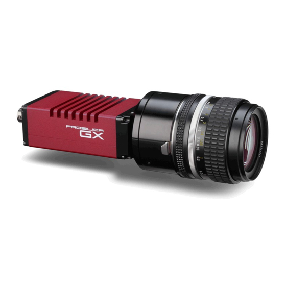
Introduction The GX3300 series of cameras are sensitive, 17 frames per second, 8 megapixel, Gigabit Ethernet cameras based on the Kodak KAI-08050 CCD sensor. These cameras support the use of 1 or 2 gigabit Ethernet ports in a LAG configuration for higher bandwidth requirements. Precautions READ INSTALLATION GUIDE CAREFULLY. -
Page 6: Specifications
Specifications Sensor Type Kodak KAI-08050 Sensor Shutter Type Progressive Interline Image Resolution 3296 x 2472 pixels Pixel Size 5.5μm x 5.5μm Optical Format 4/3 inch Lens Mount F-mount with adjustable back focus † Color Sensor Filter Pattern Bayer Full Resolution Frame Rate 17 fps 2 isolated inputs, 4 isolated outputs, RS-232 TX/RX, video auto-iris, motorized iris, focus, and zoom... -
Page 7: Supported Features
Supported Features Imaging Modes free-running, external trigger, fixed rate, software trigger Fixed Rate Control 0.001 fps to maximum frame rate External Trigger Delay 0 to 60 seconds in 1 microsecond increments External Trigger Event rising edge, falling edge, any edge, level high, level low Exposure Time 10 microseconds to 60 seconds in 1 microsecond increments Gain... -
Page 8: Mechanical
Mechanical GX F-MOUNT GX3300 Technical Manual Page 8... -
Page 9: Connections
Connections GX CONNECTION DIAGRAM GX3300 Technical Manual Page 9... - Page 10 GIGABIT ETHERNET PORTS These ports conform to the IEEE 802.3 1000BASE-T standard for Gigabit Ethernet over copper. It is recommended that CAT5E or CAT6 compatible cabling and connectors be used for best performance. Cable lengths up to 100m are supported. For higher bandwidth requirements, both ports can be used in a link aggregation group (LAG) configuration.
- Page 11 EXTERNAL POWER This connection provides the main power for the camera. The camera operates from a DC voltage between 5V to 24V. The current capacity of the power supply can be estimated by dividing the camera’s power requirement by the external power voltage. It is also recommended to factor this by about 50% as follows: Power supply current capacity = (power specification / external voltage) x 1.5...
- Page 12 SYNC OUTPUTS (1 to 4) These signals are optically isolated and require the user to provide a high voltage level (USER VCC) and signal common (USER GROUND). USER VCC can be from 5V to 24V. ICC is a function of USER VCC and load resistor R.
- Page 13 These signals only function as outputs and can be configured as follows: Exposing Corresponds to when camera is integrating light. Trigger Ready Indicates when the camera will accept a trigger signal. Trigger Input A relay of the trigger input signal used to “daisy chain”...
- Page 14 LENS CONTROL PORT FUNCTION IRIS + IRIS - FOCUS + FOCUS - ZOOM + ZOOM - AUTO IRIS SIGNAL GROUND LENS CONTROL PORT AS SEEN FROM BACK OF CAMERA This connector provides the signals necessary to control the iris, focus, and zoom of most commercially available TV Zoom lenses.
-
Page 15: Cleaning The Sensor
Cleaning the Sensor DO NOT CONTACT CLEAN SENSOR UNLESS ABSOLUTELY NECESSARY. Identifying Debris Debris on the image sensor or optical components will appear as a darkened area or smudge on the image that does not move as the camera is moved. Do not confuse this with a pixel defect which will appear as a distinct point. -
Page 16: Adjusting The F-Mount
Adjusting the F-mount THE F-MOUNT IS ADJUSTED AT THE FACTORY AND SHOULD NOT REQUIRE ADJUSTING. If for some reason, the F-mount requires adjustment, use the following method. Attach F-mount compatible lens Use an F-mount compatible lens that allows an infinity focus. Attach the lens to the camera using a counter-clockwise rotation of about a quarter turn. -
Page 17: Network Card Configuration
Network Card Configuration Operating GigE Vision GX cameras using multiple network adaptors The GX series cameras offer two Gigabit Ethernet ports for image data transfer and control. Users can connect one or both ports on the GX to Ethernet adapter ports on a host computer. Connecting both ports will increase the available bandwidth to 240 MB/sec, allowing higher frame rates and resolutions than a single port connection. - Page 18 5. Click on “OK” to validate your change (the “Properties” window will close). The Property list will be different between different types/brands of gigabit Ethernet interface cards. If "Jumbo Frames" does not appear in this list, then your card probably does not support it. If your card does not support Jumbo Frames, then your CPU usage will be higher.
- Page 19 12. Select the two Ethernet ports to which the GX camera will be connected. These ports will form our LAG or TEAM. Click “Next” to continue. 13. Choose “Static Link Aggregation”. Click “Next” to continue. 14. The LAG group will now be configured. You may be asked to permit the “AVT_Prosilica GigE Vision Filter Miniport”...
- Page 20 15. Once completed the properties of the TEAM (LAG) that has just been created will appear. A new Network Connections Icon corresponding to the LAG group is created. You have now completed the Link Aggregate Group configuration. 16. Reboot the system and install GigE Sample Viewer. GX3300 Technical Manual Page 20...
-
Page 21: Gige Sample Viewer And Filter Driver
GigE Sample Viewer and Filter Driver o Download GigE Sample Viewer from www.alliedvisiontec.com. This will install the Sample Viewer application program, drivers, and optionally the AVT/Prosilica Filter Driver. The Filter Driver will improve CPU performance and is recommended. o Plug in the GX camera Ethernet cable(s) and power. Verify that the Green LED is a solid green. -
Page 22: Trouble Shooting
Trouble Shooting Is the camera getting power? The Green LED is the camera power indicator. If unlit, check the power adaptor. If possible, swap with one that is known to work. If using a custom power adaptor, be sure the adaptor supports the voltage and power requirements of the camera . - Page 23 non AutoIP range on your NIC and it doesn’t have access to a DHCP server. Either change your NIC IP to be in the AutoIP range, or fix the camera IP address to be on the same subnet as your NIC. •...
- Page 24 • All stats 0. Likely a firewall is blocking incoming traffic. Disable your firewall. Check your camera trigger settings. Many camera trigger modes require a software or hardware trigger event to capture frames. • Packets are incoming, but all dropping. Be sure you have JumboFrames enabled on your NIC. Otherwise, decrease your PacketSize setting to 1500.
-
Page 25: Addendum
Addendum GX3300 Technical Manual Page 25... -
Page 26: Gx Io Schematic
GX IO Schematic GX3300 Technical Manual Page 26... -
Page 27: User Trigger Circuit Example
User Trigger Circuit Example This diagram indicates one example of a 5V TTL based user trigger circuit. GX3300 Technical Manual Page 27... -
Page 28: Tv Zoom Lens Connection
TV Zoom Lens Connection GX3300 Technical Manual Page 28... -
Page 29: Video Iris Connection
Video Iris Connection GX3300 Technical Manual Page 29... -
Page 30: Trigger Timing Diagram
Trigger Timing Diagram GX3300 Technical Manual Page 30... -
Page 31: Notes On Triggering
Notes on Triggering Definitions o User Trigger is the trigger signal applied by the user. o Logic Trigger is the trigger signal seen by the camera internal logic. o Tpd is the propagation delay between the User Trigger and the Logic Trigger. o Exposure is high when the camera image sensor is integrating light. - Page 32 Triggering during the Readout State o For applications requiring the fastest triggering cycle time whereby the camera image sensor is exposing and reading out simultaneously, then the User Trigger signal should be applied as soon as a valid Trigger Ready is detected. o In this case, Trigger Latency and Trigger Jitter can be up to 1 line time since Exposure must always begin on an Interline boundary.
-
Page 33: Camera Controls
Camera Controls Note: Not all features listed here are available on all camera models. Acquisition This group of controls relates to the acquiring of images. Trigger This group of controls relates to how an image frame is initiated or triggered. AcqEnd AcqEndTriggerEvent –... - Page 34 LevelHigh – active high signal LevelLow – active low signal AcqStartTriggerMode - Selects if the start of acquisition should be stimulated by an external hardware trigger. See the AcquisitionStart command for software triggering. SyncIn1 – trigger at SyncIn1 to be associated with this control SyncIn2 –...
- Page 35 Recorder – After an acquisition start event, the camera will continuously capture images into the camera on-board memory, but will not send them to the host until an AcqRec trigger signal is received. Further AcqRec trigger events will be ignored until acquisition is stopped and restarted.
- Page 36 DefectMask This feature is only available on the GE4000 and GE4900 cameras. The standard model of these cameras use Class 2 sensors which can have column defects. The DefectMask replaces defective columns with interpolated values based on neighboring columns. Class 1 and Class 0 sensors are available for these cameras which do not require any column masking.
- Page 37 Gain Auto This group of controls relates to the camera auto gain function. NOTE: The camera must be acquiring images in order for the auto gain algorithm to update. GainAutoAdjustDelay – Currently unimplemented. GainAutoAdjustTol - In percent. A threshold. Sets a range in variation from GainAutoTarget in which the auto gain algorithm will not respond.
- Page 38 IrisVideoLevelMin - In 10 mV units. Limits the minimum driving voltage for opening the lens iris. Typically this will be 0. WhiteBalance Auto The following parameters are used to control the way that the Auto whitebalance function operates. WhitebalAutoAdjustDelay - Currently unimplemented. WhitebalAutoAdjustTol - A threshold.
- Page 39 HeartbeatInterval – In milliseconds. The interval at which the API sends a heartbeat command to the camera. Normally this parameter does not require adjustment. HeartbeatTimeout - In milliseconds. The maximum amount of time the camera will wait for a heartbeat command before timing out. NOTE: this value may need to be increased when using breakpoints in your API code.
- Page 40 ImageFormat ROI - Region of Interest. Defines a rectangular sub-region of the image. Selecting an ROI that is small can increase the maximum frame rate and reduce the amount of image data. The following parameters define the size and location of the ROI sub-region: Height - In rows.
- Page 41 Sensor SensorBits - The sensor digitization bit depth. SensorHeight - The total number of pixel rows on the sensor. SensorType - Monochrome or Bayer-pattern color sensor type. SensorWidth – The total number of pixel columns on the sensor. TimeStampFrequency – In Hz. All images returned from the camera are marked with a timestamp. TimeStampFrequency is the time base for the Timestamp function.
- Page 42 FrameTrigger – Active when an image has been initiated to start. This is a logic trigger internal to the camera, which is initiated by an external trigger or software trigger event. Exposing – Active for the duration of sensor exposure. FrameReadout –...
Need help?
Do you have a question about the Prosilica GX GX3300 and is the answer not in the manual?
Questions and answers