
Related Manuals for Allied Vision Technologies Pearleye P-007 LWIR


Summary of Contents for Allied Vision Technologies Pearleye P-007 LWIR
- Page 1 AVT Pearleye Technical Manual LWIR cameras with GigE interface V2.2.0 02 May 2012 Allied Vision Technologies GmbH Taschenweg 2a D-07646 Stadtroda / Germany...
- Page 2 Allied for any damages resulting from such improper use or sale. Trademarks Unless stated otherwise, all trademarks appearing in this document of Allied Vision Technologies are brands protected by law. Warranty The information provided by Allied Vision Technologies is supplied without any guarantees or warranty whatsoever, be it specific or implicit.
-
Page 3: Table Of Contents
Safety warnings ......................11 Conformity ......................13 CE .......................... 13 Specifications .......................14 Pearleye P-007 LWIR / P-007 LWIR High Temp ..............14 Pearleye P-030 LWIR ...................... 16 Spectral transmission ....................19 Camera dimensions ..................20 Pearleye P-007 LWIR / Pearleye P-030 LWIR................ 20 Start up ........................22... - Page 4 Background correction....................36 Bad pixel correction ....................36 Drift compensation ....................36 Look-up table (LUT) ....................36 Correction data ......................37 Correction sets ......................37 File system........................37 Short introduction: Two-point correction (A, B, E, J, K, N) ......................38 Basic parameters and commands ............40 Select a correction data set (S) ..................
-
Page 5: Contacting Allied Vision Technologies
Allied Vision Technologies Inc. 38 Washington Street Newburyport, MA 01950, USA Tel.: +1 978-225-2030 Fax: +1 978-225-2029 e-mail: info@alliedvisiontec.com Allied Vision Technologies Asia Pte. Ltd. 82 Playfair Road #07-02 D’Lithium Singapore 368001 Tel: +65 6634-9027 Fax: +65 6634-902 e-mail: info@alliedvisiontec.com... -
Page 6: Introduction
Pearleye P-007 LWIR / P-007 LWIR High Temp on page 14 • Added Sensitivity (NETD) for HIGH Temp version in Chapter Pearleye P-007 LWIR / P-007 LWIR High Temp on page 14 • Added more lens options incl. FOV in Chapter Pearleye P-... - Page 7 (Q) on page 62 V2.1.1 27.01.12 Some smaller corrections: • Corrected lens f stop values of Pearleye P-007 LWIR /P-007 LWIR High Temp in Table 3: Specification Pearleye P-007 LWIR / P-007 LWIR High Temp on page 14 •...
-
Page 8: Manual Overview
Manual overview This manual overview outlines the contents of each chapter of this manual. • Chapter Contacting Allied Vision Technologies on page 5 lists AVT contact data (phone numbers and URLs) for both: – Technical information / ordering – Commercial information •... - Page 9 Image processing on page 35 describes the function of the Pearleye P-007 LWIR / Pearleye P-030 LWIR firmware. It is related to the individual modules of image processing and shows in what way the user can control these modules via the serial interface.
-
Page 10: Conventions Used In This Manual
Introduction Conventions used in this manual To give this manual an easily understood layout and to emphasize important information, the following typographical styles and symbols are used: Styles Style Function Example Bold Programs, inputs or highlighting bold important things Input Courier Code listings etc. -
Page 11: Before Operation
Introduction Before operation We place the highest demands for quality on our cameras. Target group This Technical Manual is the guide to detailed technical information of the camera and is written for experts. Getting started For a quick guide how to get started read: How to install a GigE camera (Bigeye/Pearleye/Goldeye). - Page 12 working temperature range (temperature of the camera housing) depends on the camera model: • Pearleye P-007 LWIR: 25°C ... 45°C • Pearleye P-030 LWIR: 15 °C ... 35 °C Only in this temperature range, the camera reaches optimal image quality. Outside the optimum temperature range, the image may look oversaturated..
-
Page 13: Conformity
Conformity Conformity Allied Vision Technologies declares under its sole responsibility that all standard cameras of the Pearleye family to which this declaration relates are in conformity with the following standard(s) or other normative document(s): • CE, following the provisions of 2004/108/EG directive •... -
Page 14: Specifications
Temperature stabilization Peltier stabilized 14 bit Digital output Internal 14 bit, output only 12 bit, GigE Sensor time constant approx. 7 ms Pixel clock 5.25 MHz Table 3: Specification Pearleye P-007 LWIR / P-007 LWIR High Temp Pearleye Technical Manual V2.2.0... - Page 15 Therefore the customer cannot change the lens. Changing lens and calibration has to be done in the AVT factory. • Different temperature ranges Table 3: Specification Pearleye P-007 LWIR / P-007 LWIR High Temp Pearleye Technical Manual V2.2.0...
-
Page 16: Pearleye P-030 Lwir
Specifications Note • The design and specifications for the products described above may change without notice. • The right polarization of the 12 V supply voltage must be assured. • The warranty becomes void in case of unauthorized tam- pering or any modifications not approved by the manu- facturer. - Page 17 Specifications Feature Specification Digital interface IEEE 802.3 1000BASE-T (GigE Vision V1.2) Power requirements + 12 V, -0% / +5%, max. 1.5 A Dimensions With 18 mm f/1.0 lens: 133.7 mm x 90 mm x 86 mm (L x W x H); incl. connectors Mass 790 g (with 18 mm f/1.0 lens)
- Page 18 Specifications Note • The right polarization of the 12 V supply voltage must be assured. • The warranty becomes void in case of unauthorized tam- pering or any modifications not approved by the manu- facturer. Pearleye Technical Manual V2.2.0...
-
Page 19: Spectral Transmission
Specifications Spectral transmission Figure 1: Spectral transmission of Pearleye P-007 LWIR Figure 2: Spectral transmission of Pearleye P-030 LWIR Pearleye Technical Manual V2.2.0... -
Page 20: Camera Dimensions
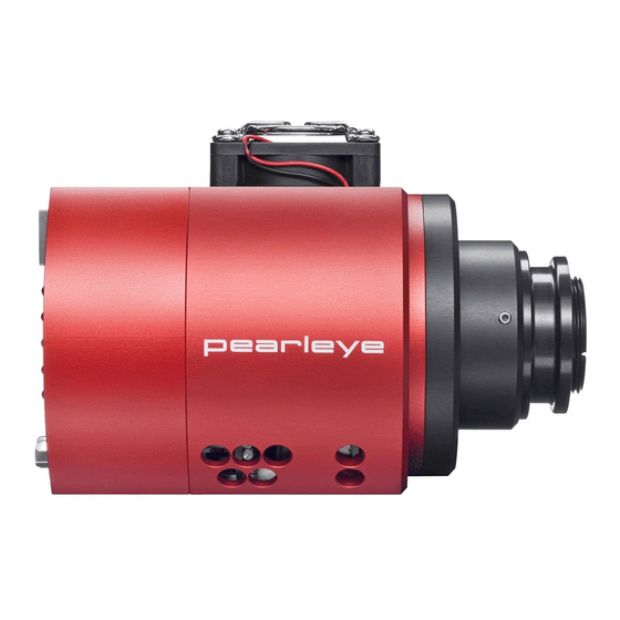
Gigabit Ethernet connection Power Power / Control Ø 9 0 connection UNC1/4" (2x) and M4 mounting holes are in the center of main body Figure 3: Camera dimensions: Pearleye P-007 LWIR / Pearleye P-030 LWIR (front/side/back) Pearleye Technical Manual V2.2.0... - Page 21 Camera dimensions Color Description Power Green Power indicator Camera is operational Temperature state Off means: temperature is ok Trigger (reset) input activity Frame output activity Table 5: Description of LEDs: Pearleye P-007 LWIR / Pearleye P-030 LWIR Pearleye Technical Manual V2.2.0...
-
Page 22: Start Up
Start up Start up A Gigabit Ethernet port (1000Base-T) on the host computer is necessary. 1. Connect the camera with the appropriate data cable to the computer. 2. Plug the 15-pin connector of the power supply to the camera. 3. Switch on the power supply. Camera control commands To configure the internal image processing, a serial command interface is pro- vided. - Page 23 Start up Serial communication operates in echo mode by default. This means that each character received by the module is echoed back to the sender. In all command examples the characters sent to the camera are represented in Bold Courier Font and the camera’s answer in Plain Courier Font.
-
Page 24: Adjust The Image Processing
Adjust the image processing Subsequently the important commands for quick starting the image correction of the Pearleye P-007 LWIR / Pearleye P-030 LWIR are mentioned. All further parameters and a description of the correction modules can be found in Chapter Image processing on page 35. -
Page 25: Camera Interfaces
Camera interfaces Camera interfaces This chapter gives you information on the control junction, inputs and outputs and trigger features. For accessories like cables see: http://www.alliedvisiontec.com/emea/products/ accessories/gige-accessories.html Pearleye Technical Manual V2.2.0... -
Page 26: Control Connector
This jack is intended for the power supply as well as for controlling the camera via its serial RS232 interface over a COM port. Furthermore some output signals are available, showing the camera state. Pearleye P-007 LWIR / Pearleye P-030 LWIR Signal Direction Level... -
Page 27: Power Supply (Pin 1-4)
Camera interfaces Power supply (pin 1-4) The camera requires 12 V +5% DC and maximum 1.5 A. The voltage should not fall below 12.0 V and should not exceed 12.6 V. It is rec- ommended to use respectively both pins (1+2, 3+4) for power supply. Serial interface (pin 7, 8) By use of the serial interface at pin 7 and 8 the camera can be controlled exter- nally via a RS232 COM port. -
Page 28: Sensor Temperature Too Low (Pin 12, 13)
41.608 ms ± 20 μs. Sensor temperature too low (pin 12, 13) Figure 6: Sensor temperature too low Caution Pearleye P-007 LWIR / Pearleye P-030 LWIR: The current which flows through the optocoupler should not exceed 20 mA 600 ). -
Page 29: Sensor Temperature Too High (Pin 14)
To resolve this, heat up the camera temperature above approx. 15 °C (Pearleye P-030 LWIR) or 25 °C (Pearleye P-007 LWIR). Use for e.g. a temperature- controlled air-flow housing. Sensor temperature too high (pin 14) -
Page 30: Conversion Of Image Data To Temperature Data
Conversion of image data to temperature data Due to the internal LUT, the pixel information can be converted to a correspond- ing temperature value. For the Pearleye P-007 LWIR the following relation can be used: T = r x DN + o with: 12-bit digital value (pixel data) Temperature value [°C]... - Page 31 Camera interfaces The following diagram shows the result: Figure 9: Conversion of image data to temperature data: Pearleye P-007 LWIR For the Pearleye P-030 LWIR the following relation can be used: T = r x DN + o with: 14-bit digital value (pixel data) Temperature value [°C]...
-
Page 32: Consideration Of The Emission Ratio
Camera interfaces The following diagram shows the result: Figure 10: Conversion of image data to temperature data: Pearleye P-030 LWIR Consideration of the emission ratio Every material has its own emissivity value for IR, so the measured value is not equal to the real temperature. - Page 33 Camera interfaces Note • Normally the background temperature can be assumed to be equal to the environmental temperature. • The emission grades of many different materials can be found on various internet sources. Pearleye Technical Manual V2.2.0...
-
Page 34: Gige Interface
Camera interfaces GigE interface The Pearleye P-007 LWIR / Pearleye P-030 LWIR cameras are equipped with a 1000Base-T Ethernet interface (RJ-45 connector). The data connection between camera and PC can be established via a standard CAT5e patch cable. Note For more information see the Pleora iPORT PT1000-VB Documentation. -
Page 35: Image Processing
Therefore an individual adjustment of each pixel is necessary. The standard firmware of the Pearleye P-007 LWIR / Pearleye P-030 LWIR contains a chain of correction modules which perform these tasks in real time. -
Page 36: Two-Point Correction
Background correction The Pearleye P-007 LWIR / Pearleye P-030 LWIR models feature an electrome- chanical shutter. In conjunction with the background correction the image quality can additionally be enhanced. The shutter is closed for a short time to acquire a temporary background correction image. -
Page 37: Correction Data
40. File system The Pearleye P-007 LWIR / Pearleye P-030 LWIR camera models are equipped with a non-volatile data memory (64 MByte flash) which records configuration and correction data. The data is managed in a minimalist file system. -
Page 38: Short Introduction: Two-Point Correction (A, B, E, J, K, N)
(A, B, E, J, K, N) The two-point correction is the most elaborate correction module of the Pearleye P-007 LWIR / Pearleye P-030 LWIR camera models. For this reason initially a general survey of the two-point correction functioning shall be given. - Page 39 Image processing Figure 13: Two-point correction The reference images are stored in several files within the flash and are directly transferred into the correction memory following the camera start-up. The parameter A indicates the file number of the correction image at low reference .
-
Page 40: Basic Parameters And Commands
Select a correction data set (S) Pearleye P-007 LWIR / Pearleye P-030 LWIR are equipped with multiple cor- rection data sets. For different operation conditions the image quality can be improved by activating another correction data set, if the environmental condi- tions have changed. -
Page 41: Automatic Calibration (K)
(one-time or timer controlled repeating) can be carried out. The automatic process tries to determine the best data set S and activates it. Pearleye P-007 LWIR / Pearleye P-030 LWIR models additional employ the electromechanical shutter to acquire a temporary background correction image. - Page 42 Table 10: GigE feature: AutoCalibrateOnce The following Pearleye P-007 LWIR table shows an overview of the time required by the command k=0: Description Time Max. Time Typical time for a Pearleye P-007 LWIR...
- Page 43 Basic parameters and commands Description Time Max. Time Typical time for a Pearleye P-030 LWIR Choose data set N1 * 2 * T 2662 ms 1331 ms (N1=16) Close shutter 5 * T 208 ms 208 ms Integrate images (N2 + 1) * T 2704 ms 2704 ms Open shutter 0 * T...
-
Page 44: Electromechanical Shutter (I)
Basic parameters and commands Electromechanical shutter (I) The Pearleye P-007 LWIR / Pearleye P-030 LWIR models are equipped with an electromechanical shutter that can be controlled with the command I. Use I=1 to close and I=0 to open the shutter. -
Page 45: Software Version And Correction Data Information (V)
Basic parameters and commands GigE feature name (CameraSpecialFeatures) Feature Visibility Description SensorTemperatureState Expert Camera sensor temperature state. 0 = The sensor temperature is 1 = The sensor temperature is outside the optimum range. QuerySensorTemperatureState Expert Query camera sensor tempera- ture state. (T = 1 command) ShutterTemperatureValue Beginner... -
Page 46: Show Help Text (?)
Basic parameters and commands Show help text (?) The command ?=1 shows a command reference text at the serial terminal. It lists a short description for each command available in the firmware. Note This function is not available as GigE Vision feature. ... -
Page 47: Advanced Parameters And Commands
Advanced parameters and commands Advanced parameters and commands This chapter describes the advanced configuration of the Pearleye P-007 LWIR / Pearleye P-030 LWIR models. Note In most cases the factory setup of the camera is sufficient. Only in special cases you need the advanced parameters and ... - Page 48 Advanced parameters and commands Value Description Deactivated Test mode: Correction data A are output as image data. (*) Deactivated Test mode: Correction data B are output as image data. (*) One-point correction: Simple subtraction of the correction data A from the input data. In addition the set value J is added as offset to each pixel value.
- Page 49 Advanced parameters and commands Example Activate the two-point correction >E=1[CR] Correction Correction Cold reference image data data Cold reference set value 0x ?????? 0x ?????? Correction Correction Warm reference image data data Warm reference set value 0x ?????? 0x ?????? Load process Figure 14: Schematic process of two-point correction The parameters A and B define both files out of which the reference images...
- Page 50 Advanced parameters and commands on page 40) actually being activated. Following the storage (X=1) and a re- start of the camera all file numbers following A and B are loaded into the correction data memory as mentioned above. For an optimum image quality one should take into consideration that the parameters A and B shall always specify a pair of two mating reference images, even though these parameters are alterable separately.
- Page 51 Advanced parameters and commands Bit position Value (12-bit) Value (14-bit) Table 18: J and K: bit usage GigE Vision feature name Feature Visibility Description TPC_OperationMode Expert Operation mode of the two-point correction (E=<value> command) TPC_CorrectionData_FileNumber Expert File number of the flash file containing the set values for the two-point correction.
-
Page 52: Background Correction (U, M)
Advanced parameters and commands Background correction (U, M) The module background correction is closely related to the module integrator / image store at the beginning of the processing chain (H). It also compre- hends an image integration function. But additionally it can subtract its current correction data image (H/U) from the incoming image and add the offset M. - Page 53 Command sequence >U=1A[CR] Pearleye P-007 LWIR ...wait for at least 34 image cycles (32 + 2 frames jitter buffer, 0.85 seconds at 40 images / second) or poll the state of bit group c with U[CR]... Pearleye P-030 LWIR ...wait for at least 34 image cycles (32 + 2 frames jitter buffer, 1.41 seconds at...
- Page 54 Advanced parameters and commands The parameter M defines the offset value that is added to each pixel if the background correction is activated. Depending on settings of parameter j, M is automatically set to the mean value of the background image, provided that the background image acquisition is done with the automatic calibration function (k).
-
Page 55: Bad Pixel Correction (C, F)
Advanced parameters and commands Bad pixel correction (C, F) The configuration of the bad pixel correction is executed ex factory, like this normally no access on behalf of the user becomes necessary. The bad pixel correction applies up to six non false neighbour pixels, in order to determine an interpolated value from the neighbours. -
Page 56: Temperature Drift Compensation (M, N, O, P)
Advanced parameters and commands GigE Vision feature name Description BPC_OperationMode Operation mode of the bad pixel correction. (F=<value> command) BPC_CorrectionData_FileNumber File number of the correction data for the bad pixel correction. (C=<value> command) Table 24: Camera special feature: BadPixelCorrection Temperature drift compensation (m, n, o, p) The output data of a microbolometer system is highly affected by the tempera- ture of the camera. -
Page 57: Look-Up Table (Lut) (D, G)
Advanced parameters and commands Note This function is currently not available as GigE Vision feature. Look-up table (LUT) (D, G) The temperature data of the microbolometer sensor is generally non-linear. The LUT linearizes the data that have already been pre-corrected by two-point, background and bad pixel correction, resulting in more exact temperature val- ues. -
Page 58: Integrator And Image Store (H)
Advanced parameters and commands GigE Vision feature name Description LUT_OperationMode Operation mode of the LUT. (G=<value> command) LUT_CorrectionData_FileNumber File number of the data for the LUT. (D=<value> command) Table 27: Camera special feature: LUT Integrator and image store (H) The integrator / image store (integrator) module is internally applied for the automatic selection of the correction set (k=) and the recording of new tempo- rary reference image data (A=FF, B=FF). - Page 59 Advanced parameters and commands The table below illustrates the possible values for the individual bit groups: Operation Mode Integrator/Image Store rw rw rw rw rw rw Bit group Value (hex) Description Output: deactivated. Data are passed through transparently. Output: activated. Output of actual image store content. Integration: deactivated.
-
Page 60: Baud Rate (S)
Advanced parameters and commands Pearleye P-007 LWIR ...wait for at least 36 image cycles (34 + 2 frames jitter buffer, 0.9 seconds at 40 images / sec.) or poll the state of bit group d with H[CR]... Pearleye P-030 LWIR ...wait for at least 36 image cycles (34 + 2 frames jitter buffer, 1.50 seconds at... - Page 61 Advanced parameters and commands Operation Mode Integrator / Image Store rw rw rw rw rw rw rw Bit group Value (hex) Description 110 Baud 300 Baud 600 Baud 1200 Baud 2400 Baud 4800 Baud 9600 Baud 19200 Baud 38400 Baud 57600 Baud 115200 Baud RS232 via 15 pin SUB-D only.
-
Page 62: Save Parameters In Flash (X)
A lot of file numbers are already reserved by factory. For the correction data of the Pearleye P-007 LWIR / Pearleye P-030 LWIR the file numbers 1, 32-96, 112-113, 128-129 are used. File numbers greater than or equal to 240 are reserved for the system itself and will be not visible to the user. - Page 63 Advanced parameters and commands Command Description v=<p8> View file. Dumps all bytes of the spec- ified file to the serial interface. Q=<p8> Upload a file and store it in the Flash memory. Table 32: File system commands Note For more details see Chapter Command reference on page 66.
- Page 64 Advanced parameters and commands The character sequence is divided into the following parts: Part Description Nnnnnnnnn n = file size in bytes – 1. Creating a file of size 0 is not specified. Sttmm t = file type (any between 01 and FE) m = transmit mode (always 00) [PAUSE] To prevent an overflow of the input buffer, a pause of at...
- Page 65 Advanced parameters and commands Note • Large files may take a while for output. • For an easy access to the file system AVT also offers an Windows application (File manager) that can be used to upload files. This is also included in the AcquireControl application and can be started by command [CTRL+F].
-
Page 66: Appendix
This firmware is used in other camera models as well. Thus not all commands and parameters mentioned in this reference are useful in conjunction with the Pearleye P-007 LWIR / Pearleye P-030 LWIR. IRC-300CL/GE, IRC-320CL/GE, IRC-340CL/GE, IRC-600CL/GE, IRC-640CL/GE, NIR-300(F)(P)CL/GE, NIR-600PCL/PGE, NIR-610PCL/PGE;... - Page 67 Appendix At the beginning of a command sequence it is good practice to check the serial communication by sending just a [CR] to the camera and verify that the command prompt ">" is returned. There is an input buffer holding a few characters but no hardware handshake.
- Page 68 Appendix h=<p16> : Internal mode and control register. (*) <**kk_jjih_gfed_cbaa> \| \||| |||| ||\| ||| |||| || +-a: Camera Link output mode. ||| |||| || 00 -> 12 data bits per pixel. ||| |||| || 01 -> 14 data bits per pixel. ||| |||| || 10 ->...
- Page 69 Appendix 10 -> 12 bits fast (e.g. NIR-300F, NIR-600; Goldeye CL-008, P-008 or P-032). 11 -> 14 bits multiplex (e.g. IRC-600, Pearleye P-030). i=<p16> : Fast AOI mode offset for Two Point Correction. This offset controls the starting point of correction data from memory, if NIR-300F/NIR-600 and Goldeye CL-008/P-008/P-032 mode is activated (see h=<p16>) and the CC2 signal from the grabber is low.
- Page 70 Appendix method. +-------f: Operation mode during image integration. See bit field "b" of parameter U=<p8> for description. +-----------g: Offset calculation method for the background correction (M=<p16>). 0 -> Set M=<p16> to the mean value of the newly captured background correction image. 1 ->...
- Page 71 Appendix represented in 16 bits fixed point two's complement notation. See parameter m=<p8> for more details about drift compensation. Changing this parameter may void ex factory calibration. p=<p16> : (IRC-320/600, Pearleye P-007/030 only:) User specified parameter for the temperature drift compensation. This is a value represented in 16 bits fixed point two's complement notation.
- Page 72 Appendix GigE interface only). 11 -> Reserved. +-----------e: Echo suppression. 0 -> Each character received from the host is echoed back to it. 1 -> No echo. v=<p8> : View file. Dumps all bytes of the specified file to the serial interface.
- Page 73 Appendix correction. Changing this parameter or the contents of the specified files may void ex factory calibration. : No loading of any correction image. The memory content remains uninitialized at startup. 01..EF : The correction data is loaded from the indicated file.
- Page 74 Appendix shares its memory with the background correction (U=<p8>). This means that a new captured image with the command H=<p8> overwrites the current image of the background correction. The difference between H=<p8> and U=<p8> is the position in the image processing chain: H integrates and outputs data always at the beginning of the chain, which is uncorrected camera raw data.
- Page 75 Appendix All set values are loaded together from the flash file N=<p8>. Changing this parameter may void ex factory calibration. K=<p16> : Define the set value for the warm (high) reference image of the two point correction. It is a 16 bits value of which the 12 (or 14) most significant bits currently are used.
- Page 76 Appendix : Show sensor temperature warning state. <***b_***a> +--a : Sensor temperature warning state (this bit is only valid for cameras with peltier temperature stabilization like e.g. IRC-300, IRC-320, IRC-600, NIR-300P, NIR-600P; Pearleye P-007/030, Goldeye (CL/P)-008 NIR Cool, Goldeye (CL/P)-032 NIR Cool). 0 ->...
- Page 77 Appendix U=<p8> : Operation mode of the background correction module. May automaticly be set to 1 by the command k, depending on the setting of parameter j. <c**a_bbba> | \_|| +---~+--a : Output mode of the background correction module. Attention: split bit field! 00 ->...
-
Page 78: Gige Vision Feature Mapping To Serial Commands
Appendix GigE Vision feature mapping to serial commands The following table shows the assignment of the available GigE Vision features to the corresponding serial commands. GigE category GigE feature name Feature Serial command (CameraSpecialFeatures) visibility TwoPointCorrection TPC_OperationMode Expert E=<value> TPC_CorrectionData_FileNumber Expert N=<value>... -
Page 79: Gige Vision Feature Description For Avt Goldeye Cameras
Appendix GigE Vision feature description for AVT Goldeye cameras DeviceInformation Feature Description DeviceModeName Name of the attached camera model. DeviceID Unique 32 bit device ID of the AVT camera model. DeviceUserID User ID field. This field can be accessed (R/W) by the user to store an additional device identifier. -
Page 80: Imagesizecontrol
Appendix ImageSizeControl Feature Description SensorWidth Maximum width of the sensor in pixels. SensorHeight Maximum height of the sensor in pixels. WidthMax This feature represents the maximum width (in pixels) of the image after horizontal binning, decimation or any other function changing the horizontal dimensions of the image. -
Page 81: Cameraspecialfeatures
Appendix CameraSpecialFeatures Feature Description AutoCalibrateOnce Start the automatic calibration once. (k=0 command) The processing of this command can take several seconds, depending on the current image rate and the number of correction data sets available. AutoCalibrationMode Configure mode of the automatic calibration function. (j=<value>... -
Page 82: Cameraspecialfeatures\Twopointcorrection
Appendix CameraSpecialFeatures\TwoPointCorrection Feature Description TPC_OperationMode Operation mode of the two-point correction. (E=<value> command) TPC_CorrectionData_FileNumber File number of the flash file containing the set values for the two-point correction. (N=<value> command) TPC_SetValue_LowRef Define the set value for the low reference image of the two-point correction. -
Page 83: Cameraspecialfeatures\Integratorandimagestore
Appendix CameraSpecialFeatures\IntegratorAndImageStore Feature Description IIS_OperationMode Operation mode of the integrator and image store. (H=<value> command) While reading this feature the MSB shows the state of the integration process. (0=Idle, 1=Busy) Table 44: Camera special feature: IntegratorAndImageStore CameraSpecialFeatures\BadPixelCorrection Feature Description BPC_OperationMode Operation mode of the bad pixel correction. -
Page 84: Index
Index Index Numbers 15-pin D-Sub jack ........26 electromechanical shutter (I) ..... 44 emission ratio.......... 32 emissivity correction ......... 32 External GND ........... 26 automatic calibration External Power......... 26 (k) ........... 41 FCC Class B ..........13 background correction....... 36 file system .......... - Page 85 Index specifications .......... 14 Spectral transmission optocoupler input........26 Pearleye P-007 LWIR......19 optocoupler output........26 Pearleye P-030 LWIR......19 start up ..........22 styles ............. 10 Support ............ 5 parameter E symbols..........10 values..........47 Parameter F values..........55 parameter U Technical information .........
Need help?
Do you have a question about the Pearleye P-007 LWIR and is the answer not in the manual?
Questions and answers