Table of Contents
Advertisement
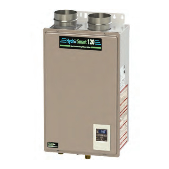
Hydro Smart 120 Condensing Gas Micro Boiler
Installation Manual and Owner's Guide
Hydro Smart 120
The
Micro-Boiler is a compact and powerful
residential unit with a versatile BTU
modulating range.
Please refer to local codes for space-heating compliance.
FEATURING
EFFICENCY: 93%
•
TEMP RANGE: 99°-140°F
•
COMPACT, SPACE SAVING
•
FLOW ACTIVATED: .75 GPM
•
COMPUTERIZED SAFETY
•
NO PILOT LIGHT
•
Satisfies the 2012 SCAQMD Rule
•
1146.2 for Ultra-Low NOx
Emissions
ANSI Z21.10.3 and CSA 4.3
Condensing Gas
Models
• HS120CON-LP (Liquid propane)
• HS120CON-NG (Natural gas)
If the information in these
instructions is not followed
exactly, a fire or explosion may
result causing property damage,
WARNING
personal injury or death.
- Do not store or use gasoline or other
flammable vapors and liquids in the vicinity
of this or any other appliance.
- WHAT TO DO IF YOU SMELL GAS
• Do not try to light any appliance.
• Do not touch any electric switch, do not
use any phone in your building.
• Immediately call your gas supplier from
a neighbor's phone. Follow the gas
supplier's instructions.
• If you cannot reach your gas supplier, call
the fire department.
- Installation and service must be performed
by a qualified installer, service agency or the
gas supplier.
If you have any questions, please
call or write to:
10725 165th Ave NW
Elk River, MN 55330
1-763-331-3066
Advertisement
Table of Contents

Subscribe to Our Youtube Channel
Related Manuals for Hydro-Smart HS120CON-LP


Summary of Contents for Hydro-Smart HS120CON-LP
- Page 1 Hydro Smart 120 Condensing Gas Micro Boiler Installation Manual and Owner’s Guide ANSI Z21.10.3 and CSA 4.3 Models • HS120CON-LP (Liquid propane) • HS120CON-NG (Natural gas) If the information in these instructions is not followed exactly, a fire or explosion may...
-
Page 2: Table Of Contents
Hydro Smart Pre-built Panels ........ - Page 3 Installation Manual CONGRATULATIONS Congratulations and thank you for choosing our condensing micro- boiler. Before use, we recommend that you read through this safety manual carefully. Please refer to the back of the manual for details about the warranty. Keep this manual for future reference. If you lose the manual, contact the manufacturer or your local distributor.
-
Page 4: Installation Manual
Installation Manual Specifications SPECIFICATIONS Hydro Smart Gas Condensing Micro-Boiler Natural Gas Input Min.: 15,000 BTU/h (Operating Range) Max.: 120,000 Propane Input Min.: 15,000 BTU/h (Operating Range) Max.: 120,000 Gas Connection 1/2" NPT Water Connection 3/4" NPT Water Pressure* 15 - 150 (0.1 - 1.0) -
Page 5: Introduction
Installation Manual Introduction INTRODUCTION • This manual provides information necessary for the installation, operation, and maintenance of the micro-boiler. • The model description is listed on the rating plate which is attached to the side panel of the micro-boiler. • Please read all installation instructions completely before installing this product. •... -
Page 6: Safety Guidelines
Installation Manual Safety Guidelines SAFETY GUIDELINES SAFETY DEFINITION Indicates an imminently hazardous situation which, if not avoided, will result in death or serious injury. DANGER Indicates an imminently hazardous situation which, if not avoided, could result in death or serious injury. WARNING Indicates an imminently hazardous situation which, if not avoided, could result in minor or moderate injury. -
Page 7: Installation
Regular maintenance is recommended for these types of environments. Sealed combustion is recommended too. 9. The Hydro Smart 120 micro-boiler is to be installed indoors only. The model is equipped with a thermistor and hi-limit switch for the exhaust gas, detecting excess temperatures within the flue and enabling the micro-boiler to safely stop operation if needed. - Page 8 • Installation and service must be performed by a qualified installer (for example, a licensed plumber or gas fitter), otherwise the warranty will be void. • The installer (licensed professional) is responsible for the correct installation of WARNING the micro-boiler and for compliance with all national, state/provincial, and local codes.
-
Page 9: Included Accessories
CLEARANCES Maintain all clearances around Back Side the micro-boiler. Side Front Model Bottom Front Back Sides HS120Con-LP 12 in. 12 in. 4 in.* 1 in. 3 in. (Liquid propane) (305 mm) (305 mm) (102 mm) (25 mm) (76 mm) 12 in. -
Page 10: Venting Instructions
VENTING INSTRUCTIONS For the 140 Indoor (T-H3M-DV) model -General- • Improper venting of this appliance can result in excessive levels of carbon monoxide which can result in severe personal injury or death. • Improper installation can cause nausea or asphyxiation, severe injury or death from carbon monoxide and flue gases poisoning. - Page 11 -Exhaust vent (ABS, PVC, CPVC, or polypropylene vent)- The micro-boiler can be vented with ABS, PVC, CPVC, or polypropylene (temperature rated up to at least 149 °F). Vent material certified to ULC S636 standards is recommended in the USA. In Canada, plastic venting must be certified to ULC S636 standards.
- Page 12 -DIPswitch settings for Vent length- Set DIPswitches shown in the tables below depending on the vent length. Only adjust switches with a black square. Black squares indicate the position of the switch. 2 inch venting Vent length Single pipe ON 1 2 3 4 5 6 7 8 9 10 5 to 6.5 ft.
- Page 13 ABS, PVC, CPVC, or polypropylene vent Typical using 2 inch vent Vent connections for single pipe 2" straight pipe * 3" elbow with bird 3"x2" reducer screen Exhaust vent collar (Female) Intake vent collar (Female) *The micro-boiler came with a metal screen that will fit into a 3 inch elbow.
- Page 14 3 inch vent Vent connections for single pipe Vent connections for two-pipe 3" straight pipe 3" straight pipe 3" straight pipe * 3" elbow with 3" coupling bird screen 3"coupling 3" coupling Exhaust Intake vent vent collar collar Exhaust (Female) (Female) vent collar Intake vent...
- Page 15 Examples of of 3 inch & 4 inch vent Two-pipe, direct-vent Single pipe with room-air intake Hanger Hanger Wall Wall Hanger Termination Terminations Roof Roof Roof flashing Roof flashing Fire stop Fire stop Refer to pages 17 and 19 for clearance information Page...
- Page 16 -Exhaust vent (Stainless steel vent)- This is a Category IV appliance and must be vented accordingly. The vent system must be sealed airtight. All seams and joints without gaskets must be sealed with high heat resistant silicone sealant or UL listed aluminum adhesive tape having a minimum temperature rating of 160 °F.
- Page 17 INSIDE CORNER DETAIL Vent terminal Air supply inlet Area where is not permitted Gas meter / regulator Canada U.S.A Direct-vent and other Direct- Other than than Direct-vent vent Direct-vent Clearance above grade, veranda, porch, deck, or 1 foot 1 foot 1 foot balcony 4 feet from below or...
- Page 18 For multiple sidewall exhaust terminations, an exhaust 2 ft. termination must be at least 1 ft. (305mm) away from (610 mm) min. 1 ft. (305 mm) another exhaust termination. An exhaust termination min. must also be at least 2 ft. (610 mm) away from an inside corner.
- Page 19 Exhaust and/or direct-vent sidewall terminations should be at least 2 ft. (610 mm) away from an opposite surface/ wall. Do not place the termination directly in front of an opening into a building Exhaust termination 2 ft. (610 mm) <For Intake air Exhaust gas Intake air...
-
Page 20: Gas Supply And Gas Pipe Sizing
GAS SUPPLY AND GAS PIPE SIZING -General- • Check that the type of gas matches the rating plate first. • Ensure that any and all gas regulators used are operating properly and providing gas pressures within the specified range shown below. Excess gas inlet pressure may cause serious accidents. - Page 21 -Natural Gas Supply Piping- Maximum delivery Capacity of Cubic Feet of Gas per Hour of IPS Pipe carrying Natural Gas with 0.60 Specific Gravity Based on Pressure Drop of 0.5" W.C. Based on Energy Content of 1,000 BTU/Cubic ft.: The micro-boiler requires 120 Cubic ft./hr Unit: Cubic feet per hour Pipe Size Length...
-
Page 22: Water Connections
-Measuring inlet gas pressure- 1. Turn off all electric power to the micro-boiler if service is to be performed. 2. Turn the manual gas valve located on the outside of the micro-boiler clockwise to the off position. The micro-boiler cannot perform properly without sufficient inlet gas pressure. Below are instructions on how to check the inlet gas pressure. -
Page 23: Pressure Relief Valve
-Pressure relief valve- The micro-boiler has a high-temperature shutoff switch built in as a standard safety feature (called a Hi-Limit switch) therefore a “pressure only” relief valve is required. • This micro-boiler does not come with an approved pressure relief valve. •... - Page 24 Discharge condensate (acidic water) in accordance with all local codes and common safety practices. WARNING The micro-boiler is a high efficiency condensing model that produces condensate (acidic water). acidic condensate generated in the secondary heat exchanger can be neutralized by the Neutralizer acces- sory.
-
Page 25: Electrical Connections
• The condensate drain is at atmospheric pressure (non-pressurized) and therefore must be allowed to drain freely with gravity only. Please ensure that there are no blockages along the condensate drain tube. All portions of the WARNING condensate drain (neutralizer and drain tube) must be at a lower elevation than the micro-boiler to prevent condensate water from building up inside the heat exchanger. -
Page 26: High-Altitude Installations
HIGH-ALTITUDE INSTALLATIONS Check the elevation where your micro-boiler is installed. Set DIPswitches shown in the tables below depending on the altitude. 0 to 2,000 ft. 2,000 to 3,000 to 5,000 to 7,500 to Altitude (DEFAULT) 3,000 ft. 5,000 ft. 7,500 ft. 10,100 ft. - Page 28 Space Heating Panel System To Boiler The Hydro Smart Dual Purpose Panel integrates with a wide variety of boilers and delivers “priority” potable heated water with no storage tank and hydronic space heating in a small reliable package. NOTICE •...
-
Page 29: Initial Operation
INITIAL OPERATION FOR YOUR SAFETY, READ BEFORE OPERATING • Check the GAS and WATER CONNECTIONS for leaks before firing unit for the first time. • Open the main gas supply valve to the micro-boiler using only your hand to avoid any spark. -
Page 30: Hydro Smart Pre-Built Panels
HS-2ZVB04 4-inch Backflow Preventer 4-inch Exhaust Sidewall Vent Terminator (Hood) and 4-inch Wall Thimble 3-inch Concentric PVC - Termination 1. Hydro Smart pre-built space heating panels: 2. 4-inch Backflow Preventer: TK-BF01 Call tech support (1-763-331-3066) for order assistance. Features: There are two functions available for this •... -
Page 31: Owner's Guide
Owner's Guide Owner's Guide CONGRATULATIONS Congratulations and thank you for choosing our condensing micro-boiler. Before use, we recommend that you read through this safety manual carefully. Please refer to the back of the manual for details about the warranty. Keep this manual for future reference. If you lose the manual, contact the manufacturer or your local distributor. -
Page 32: For Your Safety Read Before Operating
Owner's Guide OPERATING SAFETY FOR YOUR SAFETY READ BEFORE OPERATING WARNING: If you do not follow these instructions exactly, a fire or explosion may result causing property damage, personal injury or loss of life. A. This micro-boiler does not have a pilot. It is equipped with an ignition device that automatically lights the burner. - Page 33 Owner's Guide DANGER Vapors from flammable liquids will explode and catch fire causing death or severe burns. Do not use or store flammable products such as gasoline, solvents or adhesives in the same room or area near the micro-boiler. Keep flammable products: Vapors: 1.
-
Page 34: Normal Operation
Owner's Guide NORMAL OPERATION DISPLAY OF THE CONTROLLER below shows an example of the display of the controllers. The exact display may from examples. "INFO" Button Display for Temperature Each is pressed, When the STAND BY LED is ON, the mode is selected hot water set temperature will be in the following sequence. -
Page 35: Temperature Settings
Owner's Guide TEMPERATURE SETTINGS Operation Screen on the controller Turn on the 120 VAC power supply to the micro-boiler. Press the "ON/OFF" button on the controller in order to turn the controller on. When ON, the STAND BY LED is lit. It shows the set temperature on its display as shown (EX.: 120 °F) in the picture on the right. -
Page 36: Additional Features
Owner's Guide ADDTIONAL FEATURES You can get some information about the micro-boiler condition by pressing the "INFO" button. For more information, follow the procedures below: Operation Screen on the controller Inlet water temperature Inlet water temperature will be displayed on the controller by pressing the "INFO"... -
Page 37: Flow
Owner's Guide FLOW • The flow rate through the micro-boiler is limited to a maximum of 7.0 GPM (26.5 L/min). • The temperature setting, along with the return temperature of the water in the system will determine the flow rate output of the micro-boiler. FREEZE PROTECTION SYSTEM •... -
Page 38: Maintenance And Service
Owner's Guide MAINTENANCE AND SERVICE Turn off the electrical power supply and close the manual gas shutoff valve and the manual water control valve before servicing. WARNING • Be sure that all openings for combustion and ventilation air are not blocked. •... -
Page 39: Troubleshooting
Owner's Guide TROUBLESHOOTING GENERAL PROBLEM SOLUTIONS It takes a long time to • If you would like to receive hot water to your fixtures quicker, you may get hot water at the want to consider a hot water recirculation system. (p. 27) emitters. - Page 40 Owner's Guide PROBLEM SOLUTIONS Unit does not ignite • Is the power on the micro-boiler? when water goes • Is the gas on? through the unit. • Is the flow rate over 0.5 GPM (1.9 L/min)? (p. 34) • Is the system Y-strainer clean? •...
-
Page 41: Error Codes
Owner's Guide ERROR CODES -General- • The micro-boiler has self-diagnostics for safety and convenience when troubleshooting. • If there is a problem with the micro-boiler itself, or the installation of the unit, the error code will be displayed on the temperature controller. •... - Page 42 Owner's Guide -Fault Analysis of Error Codes- If the error code is displayed on the computer board of the micro-boiler and/or on the temperature controller, please check the following. After checking, consult with the manufacturer. Green Malfunction Display Diagnosis description One Time Incorrect DIPswitch •...
- Page 43 Owner's Guide Green Malfunction Display Diagnosis description Two Times Air-fuel ratio rod • Check for connection/breakage of wires (Part #708) failure and/or soot on the AFR rod (Part #108). Six Times Abnormal main gas • Check for connection/breakage of wires (Part #707) solenoid valve and/or burn marks on the computer board (Part #701).
-
Page 44: Components Diagram
Owner's Guide Components Diagram COMPONENTS DIAGRAM Case assembly 050 002 Temperature controller Page... - Page 45 Owner's Guide Components Diagram Computer board assembly Surge box assembly Page...
- Page 46 Owner's Guide Components Diagram Burner assembly Burner assembly 111 709 Manifold assembly 055 062 Page...
- Page 47 Owner's Guide Components Diagram Water Way assembly 419 465 466 064 450 053 411 058 451 413 052 453 Page...
-
Page 48: Parts List
Owner's Guide Parts List PARTS LIST Part # Item # Description Case assembly EK450 Front cover EK452 Intake air port assembly EK454 Bracket EK455 Junction box EK190 Power supply cord assembly EK456 Back guard panel EK457 Screw M4×12 (W/Washer) EW000 Screw M4×10 (W/Washer) EW001 Screw M4×10 (Coated) - Page 49 Owner's Guide Parts List Item # Description Part # O-ring P18 NBR (Black) EZP18 O-ring P20 NBR (Black) EK042 Silicon ring EKN50 Heat exchanger assembly EK467 Flow adjustment valve / Flow sensor EK129 Condensate drain port EKH23 Water inlet EKK1U Inlet drain plug EKK2B Inlet water filter...
-
Page 50: Output Temperature Chart
Owner's Guide Parts List Item # Description Part # Computer board EK480 Rubber grommet EX148 Surge box EK280 120 VAC wire EK146 120 VAC Power ON-OFF switch EKK4V Gas valve wire EK482 Flame rod wire EK483 Igniter assembly EK484 Freeze protection thermostat EKJ59 Proportional gas valve wire EK112... -
Page 51: Limited Warranty
Owner's Guide Warranty LIMITED WARRANTY 1. The manufacturer warrants this product against defects in materials or workmanship as described in this document if installed within the United States or Canada. The manufacturer or its authorized Service Representative will, at its sole discretion, repair or replace any failed or defective mechanical or electrical parts, or components thereof, or, if the manufacturer or its authorized Service Representative cannot replace said parts, and repair is not commercially practicable, the manufacturer or its authorized Service Representative will refund the purchase price. - Page 52 • Freeze damage that occurs without taking proper preventive measures as described in the installation manual. • Condensate damage due to improperly installed or lack of a condensate trap (drain). • Any product not installed in compliance with all applicable local & provincial codes, ordinances, and good trade practices.
Need help?
Do you have a question about the HS120CON-LP and is the answer not in the manual?
Questions and answers