Table of Contents
Advertisement
Quick Links
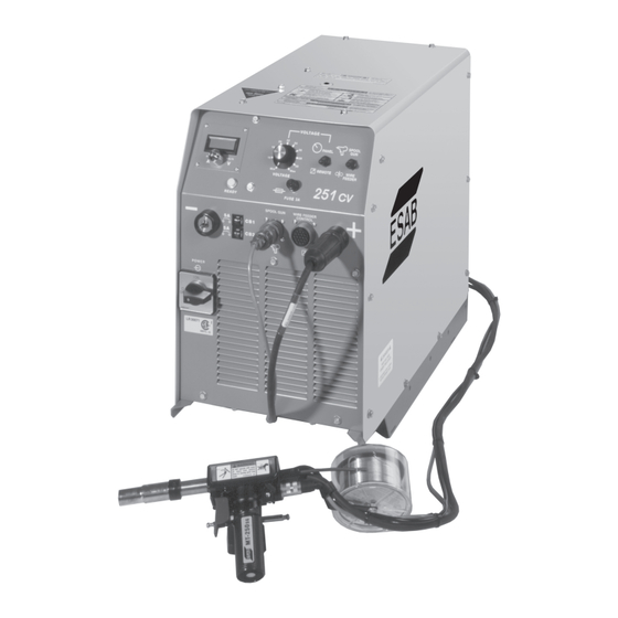
251cv shown with optional
Meter Kit and MT-250SG
Spool-On-Gun Torch
This manual provides complete instructions for the following packages starting with Serial No. MORI808001:
36696 - 251cv, 200/230/460 Vac 60 Hz
36697 - 251cv, 230/460/575 Vac 60 Hz
36698 - 251cv, 220/400 (380/415) Vac 50 Hz
These INSTRUCTIONS are for experienced operators. If you are not fully familiar with the principles of
operation and safe practices for arc welding equipment, we urge you to read our booklet, "Precautions
and Safe Practices for Arc Welding, Cutting and Gouging." Form 52-529. Do NOT permit untrained
persons to install, operate, or maintain this equipment. Do NOT attempt to install or operate this
equipment until you have read and fully understand these Instructions. If you do not fully understand
these Instructions, contact your supplier for further information.
Be sure this information reaches the operator.
You can get extra copies through your supplier.
INSTRUCTION MANUAL
251cv
POWER SOURCE
F-15-358
July, 1998
Advertisement
Table of Contents

Related Manuals for ESAB 251cv

Summary of Contents for ESAB 251cv
- Page 1 36696 - 251cv, 200/230/460 Vac 60 Hz 36697 - 251cv, 230/460/575 Vac 60 Hz 36698 - 251cv, 220/400 (380/415) Vac 50 Hz These INSTRUCTIONS are for experienced operators. If you are not fully familiar with the principles of operation and safe practices for arc welding equipment, we urge you to read our booklet, "Precautions and Safe Practices for Arc Welding, Cutting and Gouging."...
-
Page 2: Table Of Contents
Operating Procedures ........12 1.4.2 ST-23A Spool-On-Gun Torch and Adaptor Kit ..7 3.2.1 Operating Safety Precautions ......12 1.4.3 TR-24 and TR-251cv Trucks ....... 7 3.2.2 Pre-Weld Requirements ........12 1.4.4 Torch/Wire Feed Accessories ......7 3.2.3 Set-Up Procedure ..........13 Safety .............. -
Page 3: Safety Precautions
SAFETY PRECAUTIONS WARNING: hese Safety Precautions are for 5. Do not use equipment beyond its ratings. For example, your protection. They summarize precaution- overloaded welding cable can overheat and create a fire ary information from the references listed in hazard. Additional Safety Information section. - Page 4 perform any electrical work unless you are qualified to FUMES AND GASES -- Fumes and perform such work. gases, can cause discomfort or harm, 2. Before performing any maintenance work inside a power particularly in confined spaces. Do source, disconnect the power source from the incoming not breathe fumes and gases.
- Page 5 PRÉCAUTIONS DE SÉCURITÉ a. Éloigner suffisamment tous les matériaux combus- AVERTISSEMENT: Ces règles de sécurité ont pour objet tibles du secteur où l’on exécute des soudures ou des d’ assurer votre protection. Veillez à lire et à observer les coupes à l’arc, à moins de les recouvrir complètement précautions énoncées ci-dessous avant de monter l’...
- Page 6 à empêcher la forma- 52529 “Precautions and Safe Practices for Arc Weld- tion de poches d’hydrogène, lesquelles présentent un ing, Cutting and Gouging” publié par ESAB. Nous danger d’explosion; ce ventilateur ne fonctionne que conseillons également de consulter les publications si l’interrupteur correspondant du panneau avant se...
-
Page 7: Description
The ST-23A Spool-On-Gun torch can also be used with Prior to installing this equipment, clean all packing mate- the 251cv but the adaptor kit, P/N 37301, will be required. rial from around the unit and carefully inspect for any The adaptor is equipped with a gas hose for hooking up damage that may have occurred during shipment. -
Page 8: Volt/Ampere Curves
SECTION 1 DESCRIPTION TABLE 1-1. SPECIFICATIONS POWER SOURCE 251cv Rated Output 250 Amps @ 30 Volts d.c. Duty Cycle, Primary Input, Volts AC 200/230/460; 230/460/575; 220/400(380/415) Primary Input, Amperes 52/58/31; 58/31/25; 59/34(36/32) Output Current Range 30 to 300 Amps. Maximum Open Circuit Volts 36 v.d.c. -
Page 9: Installation
SECTION 2 INSTALLATION 2.1 LOCATION A proper installation site should be selected for the The lifting eyebolt is to be used for lifting power welding machine, if the unit is to provide dependable source only. Do not use when additional accesso- service and remain relatively maintenance free. -
Page 10: Input Conductor Connections
19-pin receptacle (J1) located at the center of the power source front panel. This receptacle will operate ESAB wire feeders with 19 pin control cables including TABLE 2.1 Recommended Input Fuse Size the Mig 2E, Mig 4HD, Mobile Master 2cv and Mobile Master 2cvcc. -
Page 11: Operation
SECTION 3 OPERATION 3.1.3 VOLTAGE, PANEL/REMOTE SWITCH 3.1 CONTROLS (See Figure 3.1) With this switch in the "Panel" position, output voltage is controlled by adjusting the voltage control knob on the 3.1.1 POWER SWITCH (ON-OFF) (I-O) front panel to the desired output. In the "Remote" posi- The power switch on the front panel energizes the tion, output is controlled at the wire feeder or remote primary of the main transformer and the low voltage... -
Page 12: Operating Procedures
SECTION 3 OPERATION 3.2 OPERATING PROCEDURES E. Never operate the equipment at currents greater than the rated ampere capacity. Overheating will occur. 3.2.1 OPERATING SAFETY PRECAUTIONS Comply with all ventilation, fire and other safety require- F. Never operate equipment in a damp or wet area ments for arc welding as established in the SAFETY without suitable insulation for protection against Section at the front of this manual. -
Page 13: Set-Up Procedure
G. Some welders who are accustomed to welding with stick electrodes may tend to push the torch into the NOTE: The 251cv features an automatic fan that ener- weld. This is neither necessary nor desirable, since gizes only to protect components from over- the wire electrode is being mechanically fed into the heating. - Page 14 SECTION 3 OPERATION 45° 90° FILLET WELD BUTT WELD Figure 3.2 - Continuous Weld Conditions 10° 10° TRAVEL TRAVEL Figure 3.3 - Angle of Welding Wire with Joint...
-
Page 15: Maintenance
SECTION 4 MAINTENANCE Keep power cables dry, free of oil and grease, and protected at all times from damage by hot metal and 4.1 GENERAL sparks. Clean dirt and metal particles from drive roll groove weekly; replace roll if badly worn. Be sure the branch circuit or main disconnect switch 4.3 POWER SOURCE is off or electrical input circuit fuses are removed... -
Page 16: Troubleshooting
SECTION 5 TROUBLESHOOTING If this inspection indicates trouble in the Feeder, use 5.1 GENERAL TROUBLESHOOTING Troubleshooting Guide, in the feeder manual. If welding equipment doesn’t work right despite compli- ance with checklist inspect as follows: A. With all power controls ON and other operating controls at required settings, visually check all power Many troubleshooting situations require that the cables and connections for evidence of overheating... - Page 17 ESAB representative. 2. No welding power. a. Thermostat has opened. a. Wait 15 minutes with fan running. If still no power, contact ESAB repre- sentative. b. Shorted S.C.R. in main rectifier. b. Check S.C.R. and replace if req’d. c. Open in wiring c.
- Page 18 SECTION 5 TROUBLESHOOTING TABLE 5.1 TROUBLESHOOTING GUIDE (cont.) WELD CONDITION POSSIBLE CAUSE REMEDY 10.Shield gas flow low or a. Cylinder valve closed. a. Turn off regulator. Slowly open stopped cylinder valve, until regulator gauge indicates pressure. b. Cylinder empty. b. Replace cylinder if gauge so indicates. c.
-
Page 21: Parts
Be sure to indicate any special shipping instructions To assure proper operation, it is recommended that when ordering replacement parts. only genuine ESAB parts and products be used with this equipment. The use of non-ESAB parts may void To order parts by phone, contact ESAB at 1-843-664- your warranty. - Page 22 SECTION 6 REPLACEMENT PARTS 11, 19 9, 10 7, 8 (20) - Male Plug, not shown (21) - Eye Bolt, not shown Figure 6-1. 251cv Power Source, Front View...
- Page 23 SECTION 6 REPLACEMENT PARTS Parts List for Figure 6-1. 251cv Power Source, Front View Item Qty. Part Circuit Req. Description Symbol 36795GY Base 32284GY Front Panel 13733935 Terminal Assembly, Output 952209 Receptacle, 19-Pin 647233 Receptacle 634518 Switch, SPDT, 2 Pos, 15A (Seal, Black-951474)
- Page 24 SECTION 6 REPLACEMENT PARTS 36, 37 41, 42 43, 44 Figure 6-2. 251cv Power Source, Right Side View...
- Page 25 SECTION 6 REPLACEMENT PARTS Parts List for Figure 6-2. 251cv Power Source, Right Side View Item Qty. Part Circuit Req. Description Symbol 954699 Label, Fan Hazard 951939 Blade, Fan 13732226 Fan Motor 1/16 HP 36744 Transformer 200/230/460 V T1/L1 36753...
- Page 26 SECTION 6 REPLACEMENT PARTS 60, 61 (Bottom of 58) Figure 6-3. 251cv Power Source, Left Side View...
- Page 27 SECTION 6 REPLACEMENT PARTS Parts List for Figure 6-3. 251cv Power Source, Left Side View Item Qty. Part Circuit Req. Description Symbol 36799 Shunt Flexible 37454 Shunt Meter 37313 Bus Cap Neg. 952565 Capacitor 35000µf 50WV C1, 2, 3, 4 951041 Term Block 4 Pos.
- Page 28 ESAB Welding & Cutting Products, Florence, SC Welding Equipment COMMUNICATIONS GUIDE - CUSTOMER SERVICES A. CUSTOMER SERVICE QUESTIONS: Telephone (843) 664-5540/Fax: (800) 634-7548 Order Entry Product Availability Pricing Hours: 8:30 AM to 5:00 PM EST Order Changes Saleable Goods Returns...
Need help?
Do you have a question about the 251cv and is the answer not in the manual?
Questions and answers