Table of Contents
Advertisement
This manual provides installation and operation / maintenance and troubleshooting instructions for the following units:
ESAB P/N 31950 - 208/230/460 V ac, 1 or 3 Phase, 60 Hz
ESAB P/N 31955 - 575 V ac, 3 Phase, 60 Hz (Refer to Supplement F-15-072.)
ESAB P/N 31960 - 220/380/415 V ac, 3 Phase, 50 Hz (Refer to Supplement F-15-073.)
L-TEC P/N 35618 - 220/380/415 V ac, 3 Phase, 50 Hz (Refer to Supplement F-15-073.)
These INSTRUCTIONS are for experienced operators. If you are not fully familiar with the principles of operation and safe
practices for arc welding equipment, we urge you to read our booklet, "Precautions and Safe Practices for Arc Welding,
Cutting, and Gouging," Form 52-529. Do NOT permit untrained persons to install, operate, or maintain this equipment. Do
NOT attempt to install or operate this equipment until you have read and fully understand these instructions. If you do not
fully understand these instructions, contact your supplier for further information. Be sure to read the Safety Precautions
before installing or operating this equipment.
Be sure this information reaches the operator.
You can get extra copies through your supplier.
INSTRUCTION MANUAL
SVI 450i cvcc
Power Source
F15-071-D
December, 2003
ESAB Welding &
Cutting Products
Advertisement
Table of Contents

Related Manuals for ESAB SVI 450i cvcc

Summary of Contents for ESAB SVI 450i cvcc
- Page 1 ESAB P/N 31950 - 208/230/460 V ac, 1 or 3 Phase, 60 Hz ESAB P/N 31955 - 575 V ac, 3 Phase, 60 Hz (Refer to Supplement F-15-072.) ESAB P/N 31960 - 220/380/415 V ac, 3 Phase, 50 Hz (Refer to Supplement F-15-073.) L-TEC P/N 35618 - 220/380/415 V ac, 3 Phase, 50 Hz (Refer to Supplement F-15-073.)
-
Page 2: Table Of Contents
USER RESPONSIBILITY This equipment will perform in conformity with the description thereof contained in this manual and accompanying labels and/or inserts when installed, operated, maintained and repaired in accordance with the instructions provided. This equipment must be checked periodically. Defective equipment should not be used. Parts that are broken, missing, worn, distorted or contaminated should be replaced immediately. - Page 3 WARNING: hese Safety Precautions are for your 5. Do not use equipment beyond its ratings. For example, protection. They summarize precautionary infor- overloaded welding cable can overheat and create a fire mation from the references listed in Additional hazard. Safety Information paragraph. Before performing any installa- 6.
- Page 4 FUMES AND GASES -- Fumes and gases, 2. Before performing any maintenance work inside a power can cause discomfort or harm, particu- source, disconnect the power source from the incoming larly in confined spaces. Do not breathe electrical power. fumes and gases. Shielding gases can 3.
-
Page 5: Section 1 Description
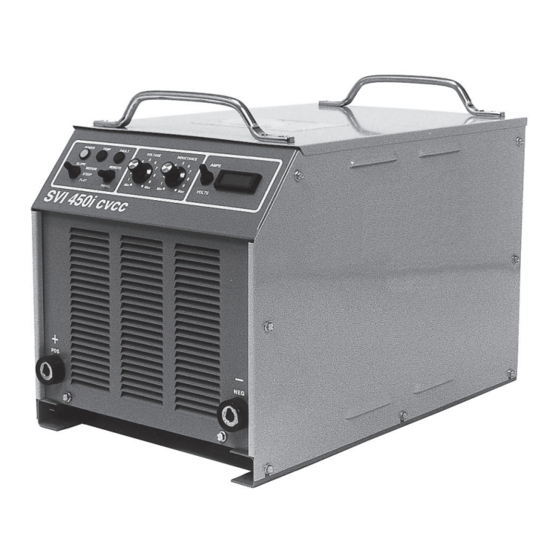
MIG welding application. Refer The SVI 450i cvcc is a high performance constant voltage to table 1-1 for specifications. (cv)/constant current (cc) 450-ampere industrial inverter power source that is designed with adjustable output 1.2 OPTIONAL ACCESSORIES... -
Page 6: Section 2 Installation
E. The location of the power source should be cannot be maintained within the 10 percent limits, consult carefully selected to ensure satisfactory and de- your local power company or call ESAB for possible pendable service. Choose a location relatively solutions. - Page 7 SECTION 2 INSTALLATION Customer's Fused Line Disconnect Switch For interconnecting control cable(s) part number(s) and Make sure all input power is disconnected hookup, refer to appropriate system instruction booklets and before performing any operation inside the power source. paragraph 2.5. Approved To Wire Feeder/ Earth Ground...
-
Page 8: Output Welding Connections
SECTION 2 INSTALLATION 2.4 OUTPUT WELDING CONNECTIONS To ensure good torch performance, periodically replace the water-cooled power cable. The welding output receptacles are located on the front panel; one negative (-) and one positive (+) receptacle. Two male plug connectors (P/N 950693) are supplied with the power source for Before making any connections to the power source attachment to customer supplied 4/0 welding... -
Page 9: Mig Control (J1) Interconnection
SECTION 2 INSTALLATION NOTE: For cc operation, either of these remote acces- sories (FC-5B or TC-2B) must be plugged in. However, for MIG operations, these particular controls must be unplugged in order to provide constant voltage. FC-5B Foot Control TC-2B Torch Control NOTE: To provide cc operation with the HC-3B or HC-4B plugged in, simply place its process switch in the CC-TIG/STICK position. -
Page 10: Additional Remote Control (J2) Interconnection
SECTION 2 INSTALLATION Table 2-3. Control Interconnection Cables Wire Feeders Digimig, Digimig Dual, Cable Lengths Mig 35 Mig 2E and Mig 4HD and Digimatic II 6-ft (1.8 m) P/N 31829 P/N 30686 30-ft (9.1 m) P/N 31830 P/N 34378 P/N 30780 60-ft (18.3 m) P/N 31831 P/N 34377... -
Page 11: Section 3 Operation
Power light (PL1) on the front panel Standard current ratings are based on a 10-minute cycle. should illuminate. The SVI 450i cvcc power source has a 60% duty cycle rating which allows 450 amperes @ 38 V dc (see Figure B. Digital Voltmeter/Ammeter (DPM) and Selec- 3-1). -
Page 12: Sequence Of Operation
SECTION 3 OPERATION to minimum for all pulse and standard spray arc D. Voltage Control Potentiometer (VCP). This welding applications. control sets and regulates the desired amount of welding voltage required for your operation. The H. Digital MIG Control Receptacle (J1). This 19- panel-faced dial surrounding the control knob pin remote control receptacle receives a mating provides a convenient reference for resetting... - Page 13 SECTION 3 OPERATION or TC-2B is unplugged from J2, or if HC-3B or B. Stick/Scratch-Start TIG Welding HC-4B is plugged in, the process switch is in the DIGITAL-MIG (center) position. 1. Depending on the process being used, make all secondary output connections to the power source 3.
- Page 14 SECTION 3 OPERATION CV MODE TIG CC MODE AMPERES AMPERES DC STICK CC MODE ARC FORCE RANGE @ A MEDIUM CURRENT SETTING AF=ARC FORCE SETTING AMPERES DC Figure 3-1. Volt-Ampere Curves DUTY CYCLE-3ø DUTY CYCLE-1ø DUTY CYCLE BASED ON 10-MINUTE PERIOD AND MAX.
-
Page 15: Section 4 Maintenance
SECTION 4 MAINTENANCE 4.1 GENERAL 4.2 CLEANING If the power source does not operate properly, stop work Since there are no moving parts (other than the fan) in the immediately and investigate the cause of the malfunction. power source, maintenance consists mainly of keeping Maintenance work must be performed by an experienced the interior of the cabinet clean. -
Page 16: Section 5 Troubleshooting
If a PC board is found to be the problem, aged or discolored components, etc. check with your ESAB supplier for a replacement. Provide the distributor with the part number of the Perform resistance checks described in the following board, as well as the serial number of the power tables. -
Page 17: Troubleshooting
SECTION 5 TROUBLESHOOTING Table 5-1. Troubleshooting Guide (Sheet 1 of 2) PROBLEM POSSIBLE CAUSE CIRCUIT CHECKS Unit inoperative - fan Incorrect primary condition or blown line Check incoming power to unit does not run fuse Incorrect linkages on voltage changeover Check links on voltage changeover board terminal board... - Page 18 SECTION 5 TROUBLESHOOTING Table 5-1. Troubleshooting Guide (Sheet 2 of 2) PROBLEM POSSIBLE CAUSE CIRCUIT CHECKS Flashing fault indicator Input voltage not within +15% and -10% of Check incoming voltage to unit - all three rated requirements phases Excessive line impedance Check voltage TB-1 (+) to TB-4(-).
- Page 19 SECTION 5 TROUBLESHOOTING Voltage Checks (T.S. deenergized) C. Power Boards, PB1/PB2, Troubleshooting (See Figures 5-1 and 5-2) (+) Probe (-) Probe Measurement TB-1(+) TB-3(-) 324 V dc TB-2(+) TB-4(-) 325 V dc Gate-1 Source-1 -12 V dc Make sure input power is disconnected (OFF) and voltage between T1 and T2 is zero.
- Page 20 SECTION 5 TROUBLESHOOTING F. SCR1 Troubleshooting (See Figure 5-1) Resistance Checks SCR1-A SCR1-K 5 ohms If reads open, then replace R1 If reads short, then replace SCR-1 SCR1-G SCR1-K diode forward drop (low impedance using diode scale) Gate Lead from Inverter Control should be disconnected Voltage Checks SCR1-G SCR1-K...
- Page 21 SECTION 5 TROUBLESHOOTING CAPACITOR MOUNTING BRACKETS P1 CONTROL PLUS (BEHIND BOARD) * To replace Power Boards (PB-1 & PB-2), disconnect cables form T1-T4, disconnect control plug P1, loosen capacitor mounting brackets behind board, remove and retain transistor mounting screws and two mounting screws at bottom of board. NEVER, UNDER ANY CIRCUMSTANCES, REMOVE OR LOOSEN ISOBARS ATTACHED TO HEAT SINK! T1, T2, POWER CABLE CONNECTIONS* Torque Specifications...
- Page 22 SECTION 5 TROUBLESHOOTING G. Inverter Control Board, ICB, Troubleshooting (See Figure 5-3) Voltage Checks (+) Probe (-) Probe Measurements P5-8 P5-9 18 V ac AC Bias P5-8 P5-10 36 V ac AC Bias P5-6 P2-9 12 V dc DC Bias P5-5 P2-9 -12 V dc...
- Page 23 SECTION 5 TROUBLESHOOTING Figure 5-3. Inverter Control Board (ICB) (Top View Layout)
- Page 24 SECTION 5 TROUBLESHOOTING...
- Page 25 SECTION 5 TROUBLESHOOTING...
- Page 26 SECTION 5 TROUBLESHOOTING...
-
Page 27: Section 6 Replacement Parts
The serial number is ordering replacement parts. stamped on the unit nameplate. To order parts by phone, contact ESAB at 1-803-664- 6.2 ORDERING 5540 or 4460. Orders may also be faxed to 1-800-634- 7548. Be sure to indicate any special shipping instruc- tions when ordering replacement parts. - Page 28 SECTION 6 REPLACEMENT PARTS 3 (SW2) 3 (SW1) Figure 6-1. SVI 450i cvcc (Front View) ITEM PART CIRCUIT REQ. DESCRIPTION SYMBOL 951526 LAMP, WHITE 951032 LAMP, RED PL2, PL3 634515 SWITCH, TOGGLE, SPDT SW1, SW2 951795 METER, DIGITAL 2062018 POTENTIOMETER, TRIM...
- Page 29 SECTION 6 REPLACEMENT PARTS REF: Matched set of capacitors is part of PB1 and PB2. Figure 6-2. SVI 450i cvcc (Top View) ITEM PART CIRCUIT REQ. DESCRIPTION SYMBOL 31135 INDUCTOR (MOUNTED ON FRONT PART OF CHASSIS BASE) 31133 TRANSFORMER, MAIN (MOUNTED ON TOP...
- Page 30 SECTION 6 REPLACEMENT PARTS Figure 6-3. SVI 450i cvcc (Top View) ITEM PART CIRCUIT REQ. DESCRIPTION SYMBOL 31143 TERMINAL BOARD, SCREEN PRINTED 38082 PC BOARD ASSY , CONTROL...
- Page 31 SECTION 6 REPLACEMENT PARTS Figure 6-4. SVI 450i cvcc (Left Side View) ITEM PART CIRCUIT REQ. DESCRIPTION SYMBOL 674991 PC BOARD ASSY, POWER 17282010 RESISTOR, 10 OHM, 100 W 950516 CAPACITOR, 0.05 µF, 600 V 950702 CAPACITOR, 0.01 µF, 125 V...
- Page 32 SECTION 6 REPLACEMENT PARTS 2 (R5), 3 3,11 2 (R4), 3 Figure 6-5. SVI 450i cvcc (Right Side View) ITEM PART CIRCUIT REQ. DESCRIPTION SYMBOL 674991 PC BOARD ASSY, POWER 17725005 RESISTOR, 5 OHM, 25 W R4,5 950516 CAPACITOR, 0.05 µF, 600 V...
- Page 33 SECTION 6 REPLACEMENT PARTS DIGITAL CONTROL REMOTE MAIN CONTROL POWER 115 AUX. Figure 6-6. SVI 450i cvcc (Rear View) ITEM PART CIRCUIT REQ. DESCRIPTION SYMBOL 950822 SWITCH, ROTOR, 3PST 680970 MOTOR, FAN 679384GY SHROUD, FAN 950592 BLADE, FAN 97W63 CONNECTOR, CABLE GRIP...
- Page 34 SECTION 6 REPLACEMENT PARTS...
- Page 35 SECTION 6 REPLACEMENT PARTS...
- Page 36 ESAB Welding & Cutting Products, Florence, SC Welding Equipment COMMUNICATION GUIDE - CUSTOMER SERVICES A. CUSTOMER SERVICE QUESTIONS: Order Entry Product Availability Pricing Delivery Order Changes Saleable Goods Returns Shipping Information Eastern Distribution Center Telephone: (800)362-7080 / Fax: (800) 634-7548...
Need help?
Do you have a question about the SVI 450i cvcc and is the answer not in the manual?
Questions and answers