NETGEAR M5300 Series Hardware Installation Manual
Managed stackable switch
Hide thumbs
Also See for M5300 Series:
- Software administration manual (720 pages) ,
- Installation manual (2 pages) ,
- User manual (764 pages)

Related Manuals for NETGEAR M5300 Series


Summary of Contents for NETGEAR M5300 Series
- Page 1 Managed Stackable Switch M5300 Series H ardware In stallation Guide 350 East Plumeria Drive San Jose, CA 95134 December 2012 202-11104-02...
-
Page 2: Technical Support
Other brand and product names are registered trademarks or trademarks of their respective holders. Technical Support Thank you for choosing NETGEAR. To register your product, get the latest product updates, get support online, or for more information about the topics covered in this manual, visit the Support website at http://support.netgear.com Phone (US &... -
Page 3: Table Of Contents
M5300 Series Front Panels ........ -
Page 4: Chapter 1 Introduction
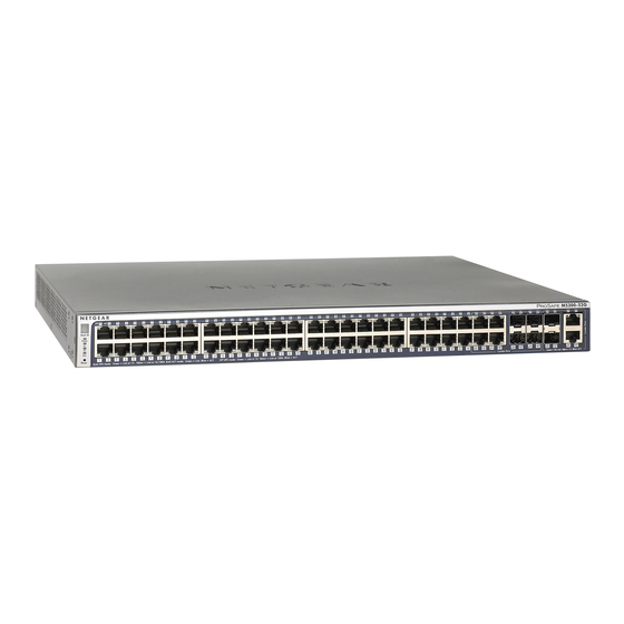
M5300 Series Front Panels The following figures show the front panels of the M5300 Series switches. The front panel contains LEDs, a Rset button, 1G copper ports or 1G fiber ports, 1G copper/fiber combo ports, and 10G copper/fiber combo ports. The SFP+ ports support any combination of ProSafe 10GBASE-SR SFP+ Module AXM761, ProSafe 10GBASE-LR SFP+ Module AXM762, or ProSafe 10GBASE-LRM SFP+ Module AXM763. - Page 5 NETGEAR Managed Stackable Switch M5300 Series LEDs 1G combo ports Copper ports Reset button 10G combo ports Figure 1. Typical series front panel Introduction...
- Page 6 NETGEAR Managed Stackable Switch M5300 Series Figure 2. M5300 series front panels Table 1. LED descriptions for M5300 Series switches Description Stack ID Stack ID is the stack member ID (1–8) that the software assigns to the switch. The decimal point to the right of the ID number lights up when the switch acts as a master unit in an M5300 Series stack.
-
Page 7: M5300 Series Rear Panel
NETGEAR Managed Stackable Switch M5300 Series Table 1. LED descriptions for M5300 Series switches (continued) Description 10/100/1000M ports Link/ACT LED: (2 LEDs per port) • Off: No link is established on the port. • Solid green: A valid link is established on the port. -
Page 8: Safety Instructions
NETGEAR Managed Stackable Switch M5300 Series Safety Instructions Use the following safety guidelines to ensure your own personal safety and to help protect your system from potential damage. To reduce the risk of bodily injury, electrical shock, fire, and damage to the equipment, observe the following precautions: Observe and follow service markings. - Page 9 NETGEAR Managed Stackable Switch M5300 Series cable approved for your country. The power cable must be rated for the product and for the voltage and current marked on the product electrical ratings label. The voltage and current rating of the cable must be greater than the ratings marked on the product.
-
Page 10: Chapter 2 Hardware Installation
Hardware Installation This chapter explains how to install the hardware for the Managed Stackable Switch M5300 Series. Package Contents Each switch is packed and shipped separately. The package contains the following items: Managed stackable switch with preinstalled software • Power cord •... -
Page 11: Unpacking The Hardware
Remove all packing material. Make sure that all items are present. See on page 10 Package Contents If any item is missing or damaged, contact your local NETGEAR Note: reseller for replacement. Inspect the products and accessories for damage. Report any damage immediately. -
Page 12: Select A Location
NETGEAR Managed Stackable Switch M5300 Series The thumbscrews on the rear modules must be tightened with a tool Note: after both initial installation and subsequent access to the modules. Select a Location The switch can be mounted in a standard 19-inch (48.26-centimeter) rack, wall-mounted, or left freestanding (placed on a tabletop). -
Page 13: Install The Switch
NETGEAR Managed Stackable Switch M5300 Series Install the Switch You can install the switch on a flat surface or in a standard 19-inch rack. Install the Switch on a Flat Surface The switch ships with four self-adhesive rubber footpads. Stick one rubber footpad on each of the four concave spaces on the bottom of the switch. -
Page 14: Check The Installation
NETGEAR Managed Stackable Switch M5300 Series Check the Installation Before you apply power, perform the following checks: Inspect the equipment thoroughly. Verify that all cables are installed correctly. Check cable routing to ensure that cables are not damaged and do not create a safety hazard. - Page 15 NETGEAR Managed Stackable Switch M5300 Series AXM761: SFP+ module with an LC connector that is compatible with the IEEE 802.3ae • (10GBASE-SR) AXM762: SFP+ module with an LC connector that is compatible with the IEEE 802.3ae • (10GBASE-LR) AXM763: SFP+ module with an LC connector that is compatible with the IEEE 802.3aq •...
-
Page 16: Create A Stack
NETGEAR Managed Stackable Switch M5300 Series Create a Stack You can connect up to eight switches to form a stack with a single management IP address. The switches automatically select a master unit. Once the master is selected, you can use its console to manage all the switches in the stack. - Page 17 NETGEAR Managed Stackable Switch M5300 Series Connect each switch to the next in a cascade to build the backplane of the stack. Finally, connect the last switch in the stack to the first switch to close the ring and provide redundancy and resiliency to the stack.
-
Page 18: Power Module Bay
NETGEAR Managed Stackable Switch M5300 Series For information about working with the CLI, see the Command Line Interface Reference for the ProSafe M5300 Series Stackable Switches on the Resource CD that shipped with your product. Power Module Bay The power module bay provides an easy way to replace a failed power module APS135W or APS525W. -
Page 19: Connect A Redundant Power Supply
NETGEAR Managed Stackable Switch M5300 Series Loosen the two captive screws on the power module. Remove the power module from the power module slot by pulling on the extraction handle. Connect a Redundant Power Supply Each switch has a redundant power supply (RPS) connector at the rear of the switch next to the power receptacle. -
Page 20: Connect A Console To The Switch
NETGEAR Managed Stackable Switch M5300 Series Connect a Console to the Switch After you install the switch and apply power, you can connect to it with a terminal or workstation. You can use the command-line interface (CLI) to identify the IP address. - Page 21 NETGEAR Managed Stackable Switch M5300 Series After you connect a console to the switch, you will need to configure it. The following documents are provided for this purpose: Installation guide: Explains basic setup and configuration (provided as both a print •...
-
Page 22: Chapter 3 Troubleshooting
Troubleshooting Troubleshooting Chart The following table lists symptoms, causes, and solutions of possible problems. Table 3. Troubleshooting chart Problem Cause Solution Power LED is off. No power is received. Check the power cord connections for the switch at the switch and the connected device. Make sure that all cables used are correct and comply with Ethernet specifications. -
Page 23: Additional Troubleshooting Suggestions
You can verify the integrity of the switch by resetting the switch. To reset the switch, use the Tools> Reset command or remove AC power from the switch and then reapply AC power. If the problem continues, contact NETGEAR technical support. •... -
Page 24: Appendix A Technical Specifications
Technical Specifications Specifications for M5300 Series Table 4. M5300 Series technical specifications Feature M5300 IEEE Network Protocol • 802.3i 10BASE-T and Standards • 802.3u 100BASE-TX compatibility • 802.3z 1000BASE-X • 802.3ab 1000BASE-T • 802.3ae 10GBASE-SR • 802.3ae 10GBASE-LR • 802.3aq 10GBASE-LRM •... - Page 25 NETGEAR Managed Stackable Switch M5300 Series Table 4. M5300 Series technical specifications (continued) Switch management • Port mirroring (TX, RX, Both) • CPU port mirroring • SNMP v1, v2c, v3 • RFC2819 RMON Groups 1, 2, 3, and 9, RFC1213 MIB II •...
- Page 26 NETGEAR Managed Stackable Switch M5300 Series Table 4. M5300 Series technical specifications (continued) System Service • DHCP, BOOTP Relay • DHCP Server Stacking • Maximum of 8 switches in a single stack • RING Topology support • CHAIN Topology support...
- Page 27 NETGEAR Managed Stackable Switch M5300 Series Table 4. M5300 Series technical specifications (continued) Bandwidth • 136 Gbps (M5300-28G3/M5300-28G/M5300-28GF3/M5300-28G-POE+) • 184 Gbps (M5300-52G3/M5300-52G/M5300-52G-POE+) Dimensions (W x D x H) 440 x 391 x 43 mm (17.3 x 15.4 x 1.7 in.)
- Page 28 NETGEAR Managed Stackable Switch M5300 Series Table 5. Technical specifications - model specific Feature M5300-28G-POE+ M5300-28G3 M5300-52G-POE+ M5300-52G3 M5300-28G M5300-52G M5300-28GF3 Maximum power M5300-28G-PoE+: 535W M5300-28G3: 55W consumption M5300-52G-PoE+: 556W M5300-52G3: 79W M5300-28G: 55W M5300-28GF3: 80W M5300-52G:79W Mean time between MTBF at 55°C...
-
Page 29: Appendix B Default Configuration Settings
Default Configuration Settings Table 6. Default settings Feature Default Setting Port speed Auto-negotiation Port duplex Auto-negotiation Flow control (half duplex) Enabled Flow control (full duplex) Disabled Broadcast storm control Enabled Gigabit port type Auto detect Management IP DHCP configuration Password protection Disabled User name Admin... - Page 30 NETGEAR Managed Stackable Switch M5300 Series Table 6. Default settings Feature Default Setting GMRP Disabled IP routing Disabled MAC address aging 300 seconds SNMP community public (read-only access), private (read/write access) DHCP server Disabled VLAN ingress filtering Enabled IP multicast filtering Disabled 802.1x...
-
Page 31: Appendix C Notification Of Compliance
Notification of Compliance Certificate of the Manufacturer/Importer It is hereby certified that the NETGEAR M5300 Managed Stackable Switches have been suppressed in accordance with the conditions set out in the BMPT-AmtsblVfg 243/1991 and Vfg 46/1992.The operation of some equipment (for example, test transmitters) in accordance with the regulations may, however, be subject to certain restrictions. - Page 32 EN 55 022 Declaration of Conformance This is to certify that the NETGEAR M5300 Managed Stackable Switches are shielded against the generation of radio interference in accordance with the application of Council Directive 89/336/EEC, Article 4a. Conformity is declared by the application of EN 55024 Class A (CISPR 22).
Need help?
Do you have a question about the M5300 Series and is the answer not in the manual?
Questions and answers