Table of Contents
Advertisement
Quick Links
Download this manual
See also:
Installation Manual
Advertisement
Table of Contents

Related Manuals for Renovo Digiwatts RN5000US


Summary of Contents for Renovo Digiwatts RN5000US
- Page 1 PV grid-connected inverter Digiwatts RN5000US Installation Guide Installation Guide RN5000US...
- Page 2 Reproduction and storage in a retrieval system, or transmittal, even partially, of the contents of this manual is strictly forbidden without prior authorization of Renovo Power Systems. All such warranties are expressly disclaimed. Neither Renovo Power Systems nor its distributors or dealers shall be liable for any indirect, incidental, or consequential damages under any circumstance.
-
Page 3: Important Safety Instructions
A Warning describes a hazard to equipment or personnel. It calls attention to a procedure or practice, which, if not correctly performed or adhered to, could result in damage to or destruction of part or all of the Renovo Power equipment and/or other equipment connected to the Renovo Power equipment or personal injury. - Page 4 In addition to the safety and hazard symbols described on the previous pages, the following symbols are also used in this Installation Guide. Make sure to read the labels and fully understand them before installing the equipment. INFORMATION This symbol calls attention to supplementary information that you should know and to ensure optimal operation of the unit.
- Page 5 Canadian standards. The Digiwatts unit contains no user-serviceable parts. For all repair and maintenance always return the unit to an authorized Renovo Power Service Center. Before installing or using the Digiwatts unit, read all of the instructions, cautions, and warnings on the Digiwatts unit, the PV array and in this Installation Guide.
-
Page 6: Table Of Contents
Table of Contents 1 Introduction ..................... 8 1.1 Validity ....................8 1.2 Target group .................... 8 1.3 Product overview ..................9 1.4 Feature Overview .................. 13 1.5 Safety ....................13 1.5.1 Protection and criterion ..............13 1.5.2 Safety instructions ................ 16 1.5.3 Symbols on the Type Label ............ - Page 7 5.4.1 DC Connection Requirements ............39 5.4.2 Connecting the DC Wires ............. 43 5.5 Communication Wiring ................43 5.6 Closing the Digiwatts unit ................ 45 6 Commissioning ..................... 47 7 Displays and Messages ................49 7.1 LED Operation Indicators ................ 49 7.2 Status Messages on the LCD Display ............
-
Page 8: Introduction
1 Introduction 1.1 Validity This manual describes the assembly, installation, commissioning and troubleshooting of the following Renovo inverter: Digiwatts RN5000US. Information To help avoid problems during the installation, familiarize yourself with the installation process by reading the entire Installation Guide before starting the installation. -
Page 9: Product Overview
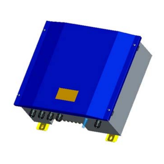
1.3 Product overview Basic information The Digiwatts inverter is used to convert DC power generated by the PV arrays into stable AC power for output to the utility grid. The Digiwatts system is a transformerless inverter and performs this conversion in a very efficient way, without moving components, using only solid state power electronic devices. -
Page 10: Electrical Block Diagram
Electrical block diagram Figure 1-2 shows the main circuit of Digiwatts transformerless grid-connected inverter system. A boost circuit raises input DC voltage within the inverter. Then a Maximum Power Point Tracker (MPPT) ensures that maximum power is extracted from the PV arrays. - Page 11 Terminals of the Digiwatts system Figure 1-3 Product Description Table 1-1 Terminals Description Item Name Description DC inputs Two pairs of DC strain reliefs are the input ports LCD display Running data is displayed on the LCD screen AC outputs Output port strain relief of the Digiwatts unit RS485 terminal Standard communication interface Installation Guide...
- Page 12 Dimensions and weight Figure 1-4 Dimensions of the Digiwatts unit Table 1-2 Dimensions Value Depth Width Height Weight Type (mm / inch) (mm / inch) (mm / inch) (kg / lb.) RN5000US 218 / 8.6 532 / 20.9 458 / 18 27 / 59 Installation Guide RN5000US...
-
Page 13: Feature Overview
1.4 Feature Overview The Digiwatts system represents state-of-the-art technology. Several key features: High reliability and safety High efficiency Simple installation Quiet operation LCD Display Powder coated die-cast enclosure Operating Temperature The Digiwatts system has been equipped with a passive radiator used to maintain full power output at ambient temperatures as high as 45°C. - Page 14 the output of the Digiwatts perfectly. The Digiwatts system incorporates an advanced active islanding protection algorithm to ensure that the system will not export power into a balanced 60 Hz resonant load while the utility is disconnected. The Digiwatts system periodically injects both leading and lagging reactive current into the utility grid.
- Page 15 application. To protect the DC system, surge suppression devices (SPD Type 2) should be fitted at both the inverter end and array end of the DC cabling. If the voltage protection level (VP) of the surge arresters is greater than 1100 V, an additional SPD Type 3 is required for surge protection for electrical devices.
-
Page 16: Safety Instructions
the meter/distribution system; SPD (test impulse D1) for signal line according to EN 6164321. All DC cables should be installed to provide runs as short as possible, and positive and negative cables of the same string or main DC supply should be bundled together, avoiding the creation of loops in the system. - Page 17 CAUTION Possible damage to health as a result of the effects of electro-magnetic radiation! Do not stay closer than 20 cm to the inverter for an extended of time. CAUTION Risk of Electric Shock! Do not remove cover No user serviceable parts inside. Refer servicing to qualified service personnel.
-
Page 18: Symbols On The Type Label
1.5.3 Symbols on the Type Label Table1-3 Symbols on the Type Label Icon Explanation The product works with high voltages. All work on the product may only be done as described in the documentation. The product can generate heat during operation. Avoid coming into contact with the product during operation. -
Page 19: Installation Overview
1.6 Installation Overview This section provides an overview of the installation process and User Manual contents. Section 1: Unpacking and Inspection Provides instructions for unpacking and inspecting the Digiwatts system for shipping damage. Section 2: General Use Read this manual carefully before using this product. If you encounter any problem during installing or running this unit, please check this manual first before contacting your local dealer or representative. -
Page 20: Unpacking And Inspection
Section 8: Technical Specifications Provides functional technical data plus connection diagrams and torque specifications for the connection of cables and fasteners of the Digiwatts unit. 2 Unpacking and Inspection NOTICE! The distributor delivered your Digiwatts unit to the carrier fully functional and securely packaged. - Page 21 If you need assistance with a damaged Digiwatts unit, contact Renovo Power. Contact information for Renovo Power is provided below. North America:...
-
Page 22: Scope Of Delivery
2.1 Scope of Delivery Table 2-1 Delivery Contents Item Description Note RN5000US Digiwatts Inverter unit Bracket Used for mounting inverter onto the wall Expansion screws Fastening bracket onto the masonry wall M6 machine screws Fastening Digiwatts system onto the bracket User manual Installation and operation instructions Warranty/Service statement... -
Page 23: Ac Voltage Configuration
3 AC Voltage Configuration 3.1 Opening the Digiwatts Unit Figure 3-1 Opening the Digiwatts Unit 1) Remove the four machine screws and lock washers from the housing cover and pull the cover forward smoothly. 2) Remove any communication or power cables possibly connecting the front cover LCD board. -
Page 24: Locating Internal Components
grounded properly and is fully sealed to the case. Handle the cover carefully, as even seemingly minor damage to the cover could result in an inadequate seal between the cover and the case, thus allowing moisture to enter the case and damage the sensitive electronic components. NOTICE! Do not install the Digiwatts unit during periods of precipitation or high humidity (>95%). -
Page 25: Configuring The Ac Voltage
Table 3-1 Internal Components Item Description PV enclosure inputs Heat sink Power Supply Board RS485 AC Out Main board DSP Board 3.3 Configuring the AC Voltage The Digiwatts system is compatible with 240V AC output. The Digiwatts unit comes from the factory pre-configured for utility interconnection at 240V AC. Figure 3-3: Common Utility Voltage Configurations Information When using 240 V Delta Corner grounded grids, connect the N terminal to... -
Page 26: Mounting
4 Mounting This section provides guidelines to help you select the best mounting location, suggestions to insure best performance, cautions and warnings that you should follow to avoid injury and/or equipment damage, and step-by-step instructions for mounting a Digiwatts inverter. WARNING! The Digiwatts unit weighs up to 27 kg. - Page 27 NOTICE! This unit is designed for indoor or outdoor usage. But it is suggested that the unit not be exposed to rain or water directly and use of a shelter to protect the unit would be preferred. Do not expose this unit to the sun directly. This may reduce the output power due to high temperature.
-
Page 28: Dimensions And Required Clearances
4.2 Dimensions and Required Clearances CAUTION! If you are installing the Digiwatts unit in a cabinet, closet, or other relative enclosed area, sufficient air circulation must be provided to dissipate the heat generated by the inverter. Figure 4-2 shows the outer dimensions of the Digiwatts unit. The unit must be mounted so that there are at least 50cm of clearance at all points. - Page 29 Figure 4-3 Dimensions of the Wall Mounting Bracket Information You must ensure that there is sufficient clearance for the flow of the air around the Digiwatts unit! In a normal operating environment with good ventilation, 50 cm of clearance is sufficient. The National Electrical Code may require increased working clearances.
-
Page 30: Mounting Procedure
4.3 Mounting Procedure 4.3.1 Mounting the Wall-Mounting Screw The Digiwatts unit is shipped with expansion screws suitable for use with most walls. Make sure that the wall you choose to mount the Digiwatts unit on is sturdy enough to support its weight (27 kg) over a long period of time and that the wall is plumb. The screws may also be mounted on masonry, brick or solid walls. -
Page 31: Mounting The Digiwatts Unit To The Wall Bracket
Table 5-1 Mounting Items Item Description Concrete / block wall Expansion cylinder Bracket Washer Spring washer Hexagonal nut Mounting the expansion screws: Three fasteners are required to secure the wall mounting bracket to a wall: Two fasteners along the top of bracket using the center holes on each side (centerline spacing of 252mm) and a third fastener at the centerline of the bottom of the bracket (Expansion screws are provided however it is installers responsibility fasteners are appropriate for wall material.) Ensure that all fasteners are well secured. -
Page 32: Wiring The Digiwatts Unit
WARNING! The Digiwatts unit weighs up to 27 kg. To avoid injury, be sure to use proper lifting techniques and secure the help of someone to assist in the unpacking and installation of the inverter. 2) Secure the bottom tabs protruding from the bottom of the Digiwatts units to the bracket using two M6 machine screws. - Page 33 WARNING! Before connecting or operating the Digiwatts unit, read all of the instructions, cautions, and warnings on the Digiwatts unit, the PV array and in this Installation Guide. WARNING! You must connect the wires that carry the AC voltage from the Digiwatts unit to the utility grid and the wires that carry the DC voltage from the PV array to the Digiwatts unit in the order described in the procedures in this section.
- Page 34 Information The DC input and AC output circuits are isolated from the enclosure and system grounding, as required by section 250 of the National Electric Code, ANSI/NFPA 70. Similarly, such isolation of DC input and AC output circuits from enclosure and system grounding is also required by the CANADIAN ELECTRICAL CODE, PART 1.
-
Page 35: Sequence Of Connecting
5.1 Sequence of Connecting Figure 5-1 Electrical Connection Diagram 1) De-energize all energy sources by opening all AC and DC disconnects and/or breakers. 2) Wire from AC breaker to the AC disconnect switch. 3) Wire from the AC disconnect switch to the Digiwatts unit. 4) Wire from the PV wires to the DC disconnect. -
Page 36: Opening The Digiwatts
5.2 Opening the Digiwatts 1) Remove the four machine screws from the housing cover and pull the cover forward smoothly. 2) Disconnect the three connections on the front cover LCD display board. Note that each connector is unique and only able to reconnect to a single position. -
Page 37: Wiring The Ac Output
Figure 5-2 (b) Front Cover Electrical Connections 5.3 Wiring the AC Output This subsection provides complete, step-by-step procedures for wiring the AC output from the Digiwatts unit to the utility grid. 5.3.1 AC Connection Requirement WARNING! All electrical installations must be done in accordance with all local electrical codes and with the National Electrical Code (NEC), ANSI/NFPA 70. -
Page 38: Connecting The Ac Wires
WARNING! To reduce the risk of fire, connect only to a circuit provided with the required branch circuit over-current device sized in accordance with the National Electric Code, ANSI/NFPA 70. The maximum size over-current device shall not be more than 50 amperes. WARNING! You must connect the wires that carry the AC voltage from the Digiwatts unit to the utility grid in the order described in this procedure. -
Page 39: Wiring The Dc Input
Figure 5-3 AC Connection Terminals 5.4 Wiring the DC input This subsection provides procedures for wiring the DC input from the PV array to the Digiwatts unit. The figure 5-4 below shows a simplified wiring diagram of a PV system. 5.4.1 DC Connection Requirements WARNING! All electrical installations must be done in accordance with all local electrical... - Page 40 WARNING! Use #10 AWG, 105 °C, copper wire for all DC wiring connections to the Digiwatts. Voltage drop and other considerations may dictate that larger size wires be used. Use only solid or stranded wire but not fine stranded wire. WARNING! The DC disconnect for the inverter must have a minimum rating of 600VDC and 36A continuous.
- Page 41 CAUTION! Verify the polarity and the open-circuit voltage from the PV strings before you connect the DC wires to the Digiwatts unit. Applying an open-circuit DC-input voltage that exceeds the maximum DC-input-voltage range will cause irreversible damage to the Digiwatts unit and void the warranty! Always configure the DC-input-voltage range correctly before connecting the DC-input wires from the PV array to the Digiwatts unit.
- Page 42 You will find the necessary DC strain relief connectors for DC connection in the delivery package. The following limit values at the DC input of the inverter must not be exceeded: Maximum input current Maximum input voltage Left 2 inputs Right 2 inputs 500V 13 A...
-
Page 43: Connecting The Dc Wires
5.4.2 Connecting the DC Wires 1) Verify that the AC breaker(s) are OFF. 2) Verify that the DC disconnect is open in the external DC disconnect enclosure. 3) Pull the DC wires from the DC disconnect through the conduit into the interior of the Digiwatts unit. - Page 44 Figure 5-6 Communication Wiring Wiring procedure: 1) A resistance with 120Ω is connected at the initiating terminal of RS485 bus. 2) Plug the connector of the RS485 cable into corresponding RS485 terminal of Inverter 1 3) The two lines of the other end of RS485 cable, labeled A and B, are connected to corresponding lines of RS485 bus, as the above diagram.
-
Page 45: Closing The Digiwatts Unit
5.6 Closing the Digiwatts unit When you have finished connecting the AC-output wires, the DC-input wires, re-check all your connections to ensure that everything is in the right place and that all connections and knockout fittings are secure and properly torqued. Check all of the knockout fittings on the bottom of the Digiwatts unit to ensure that they provide a weather-tight seal. - Page 46 seal, as all of this hardware is necessary to ensure proper grounding and a weather-tight seal. 4) Check the enclosure seal on the inside of the cover to ensure it is undamaged and in the correct position. 5) Carefully position the cover on the front of the Digiwatts unit so that the four holes in the cover are aligned correctly with the four threaded holes in the case.
-
Page 47: Commissioning
6 Commissioning WARNING! Follow the steps in the commissioning procedure in the order they are presented. Deviating from these procedures could expose you to lethal voltages that can cause serious injury and/or death. CAUTION! Follow the steps in the commissioning procedure in the order they are presented. - Page 48 greater than 250V DC, the Digiwatts unit will automatically begin feeding power to the utility grid. Information The Digiwatts unit operates from the power produced by the PV array and is designed for minimal internal DC-power consumption. The maximum power that the Digiwatts unit will consume in normal operation is 8W.
-
Page 49: Displays And Messages
7 Displays and Messages Each Digiwatts inverter comes equipped with three LED status indicators. This shows users the main status when the inverter is working. The basic definitions of the indicator lights are as follows: Figure 7-1 Front Cover LED Status Indicators The upper green LED indicates the Digiwatts unit is waiting, and the middle green LED indicates the Digiwatts unit is running. -
Page 50: Status Messages On The Lcd Display
power, but not yet powerful enough to begin normal operation. Data transmission is not possible during initialization. Occasionally, during inclement weather or low irradiation, the LEDs may all turn on at once and then go off again. This indicates that the inverter is trying to initialize but the power available from the array is not sufficient for normal operation. - Page 51 LCD Display Parameters DIGIWATTS RN5000US Hour: 0000.0h Grid: 000V 00.0A Power: 0000W Ttl: 00000kWh PV2: 000V 00.0A PV1: 000V 00.0A Fault: OK Status: Wait Renovo Power Systems Parameter Description Table 7-1 Parameter Descriptions Item Parameter Description Model Inverter Model Grid...
-
Page 52: Fault Messages On The Lcd Display
7.3 Fault Messages on the LCD Display If the Status message is “Stop”, the inverter has a fault and the specific issue will be displayed at Fault parameter location. DIGIWATTS RN5000US Hour: 0000.0h Grid: 243V 00.0A Power: 0000W Ttl: 00000kWh PV2: 002V 00.0A... -
Page 53: Troubleshooting
3. If the system problem persists, contact RENOVO POWER technical support at: 810-923-2643 In order to better assist you when contacting RENOVO POWER, please provide the following information: Required Information for Digiwatts unit Service: Serial number... - Page 54 Information Regarding the PV modules: Manufacturer name and model number of the PV module Output power of the module Open circuit voltage (Voc) of the module Number of modules in each string If it becomes necessary to send the Digiwatts unit back to the manufacturer for service, please ship it in the original packaging to avoid damage during shipping.
-
Page 55: Error Messages
8.2 Error Messages If a fault occurs, the Digiwatts system generates an error message according to the operating mode and the detected fault. Fault Code Description No_Ug There is no grid. Ug_L The AC grid voltage is too low Ug_H The AC grid voltage is too high Ig_H Over current on the AC side... -
Page 56: Technical Specifications
9 Technical Specifications 9.1 Digiwatts Wiring Diagrams Installation Guide RN5000US... -
Page 57: Specifications
9.2 Specifications Item Description Specification Maximum input voltage 500V Range of input operating voltage 200-450V Maximum input current (dc) 2*10A Maximum array short circuit current (dc) 2*12.5A Maximum utility backfeed current (ac) Output power factor rating (ac) Operating voltage range (ac) 215-265V Operating freq. -
Page 58: Trip Limits / Trip Times
9.3 Trip Limits / Trip Times Nominal Trip Limit (Hz) Trip Freq. (Hz) Trip Times (s) Freq. (Hz) > 60.5 60.45 - 60.55 max. 0.1602 < 59.3 59.25 - 59.35 max. 0.1602 Nominal Trip Voltages Trip Limit Trip Times (s) Voltage (V) Line-to-Neutral (V)* 119 - 121...
Need help?
Do you have a question about the Digiwatts RN5000US and is the answer not in the manual?
Questions and answers