Advertisement
Quick Links
TH131
Pilot wire indicator
(Europe only)
TH133
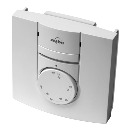
Front View
NOTE: Even if the following illustrations show the TH131 model only,
they can also apply to the TH133 model.
Description
This user guide covers the following thermostat models:
• TH131 A/F/AF
• TH133 A/F/AF
The TH131 model is designed for residential applications, whereas
the TH133 model is designed for public areas as its controls are hid-
den and thus protected against unauthorized access. Both models
can be configured for the following applications:
Type
A
Controls the ambient (room) temperature
F
Controls the floor temperature
AF
Controls the ambient temperature and limits the floor temperature
TH131 & TH133
Heating indicator
On/Off switch
Temperature
selection dial
Rear View
Application
Installation
Control Module
NOTE: Keep the thermostat's air vents clean and free from obstruc-
tions.
Configuration
3.1
Application Types
1.
Position the switch, on the back of the control module, according to
your application.
3.2
Minimum and Maximum Limits (TH131 only)
Use the two potentiometers on the
back of the control module to set
the minimum and maximum tem-
perature limits. Depending on your
application,
the
limit the following temperature:
ambient temperature (A)
floor temperature (F or AF)
Use a flat-tip screwdriver to rotate
the potentiometers until the notch
points to the desired temperature
limit.
TH131 & TH133
Electronic Thermostat
Power Base
Type
Switch Position
A
UP (A/AF)
AF
UP (A/AF)
F
DOWN (F)
potentiometers
400-131-002-C
User Guide
2.
3.
notches
1/11/06
1/2
Advertisement

Related Manuals for Aube Technologies TH131


Summary of Contents for Aube Technologies TH131
-
Page 1: User Guide
Configuration Application Types Rear View Front View Type Switch Position NOTE: Even if the following illustrations show the TH131 model only, they can also apply to the TH133 model. UP (A/AF) UP (A/AF) Description DOWN (F) This user guide covers the following thermostat models: Position the switch, on the back of the control module, according to your application. -
Page 2: Specifications
Email: advaube@comintes.com Email: aube.service@honeywell.com • TH131: 78.9 x 78.9 x 16.3 mm (3.1 x 3.1 x 0.64 in.) • TH133: 78.9 x 78.9 x 18 mm (3.1 x 3.1 x 0.71 in.) For more information on our products, go to www.aubetech.com... -
Page 3: Installation Instructions
PB130-024T Installation Instructions 24-V Low-Voltage Power Base Single SSR with Built-in Transformer Applications This document describes the connections when the PB130-024T power base is used on any TH13x series thermostat. This low-voltage power base can be connected to a line-voltage load using a relay or directly to a 24-volt device.
Need help?
Do you have a question about the TH131 and is the answer not in the manual?
Questions and answers