
Related Manuals for Polar Air PTTW-10-EC Series


Summary of Contents for Polar Air PTTW-10-EC Series
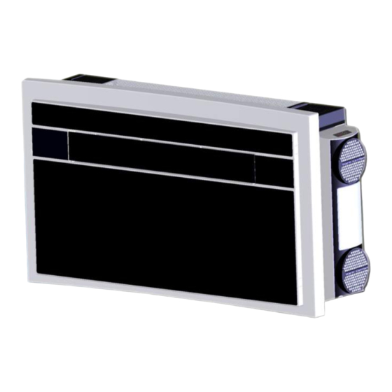
- Page 1 USER & INSTALLATION MANUAL PTTW-10-EC+EH SERIES THROUGH THE WALL HEAT PUMPS 2010 ARI-V1.5...
- Page 2 INVESTING IN QUALITY, RELIABILITY & PERFORMANCE. World Leading Design and Technology ISO 9001 QUALITY Equipped with the latest CAD/CAM computer aided design and manufacturing technology, our factories in China and Thailand produce over 2,000,000 air Every product is manufactured conditioning units each year, all conforming to the highest to meet the stringent international standards of quality and safety.
- Page 3 INDEX PTTW SERIES THROUGH THE WALL UNIT PAGE INTRODUCTION SAFETY INSTRUCTIONS RECEIVING THE GOODS HANDLING LIST OF ACCESSORIES TECHNICAL FEATURES POSITIONING THE UNIT INSTALLATION TEMPLATE DRILL THE WALL FASTENING THE BRACKET INSTALLATION OF THE PIPES FITTING THE GRATINGS FITTING THE UNIT ON THE BRACKET INTRODUCTION OF LCD ICONS REMOTE CONTROL FUNCTIONS STANDARD HEATING MODE...
-
Page 4: General Information
GENERAL INFORMATION 1.1 INTRODUCTION Do not attempt to repair or adjust any electrical or PLEASE NOTE. Do not dispose of any packaging mechanical functions on this unit as this may void until installation of the unit is completed. warranty, contact your service engineer. After having removed the packing, check that all Always operate the product from a power source the contents are intact and complete. - Page 5 GENERAL INFORMATION 1.3 RECEIVING THE GOODS 1. FASTENING BRACKET The unit is delivered in a protective packaging and 2. REMOTE CONTROL is accompanied by an instruction manual. This 3. REMOTE CONTROL HOLDER manual is an integral part of the unit and should 4.
-
Page 6: Fan Speed Setting
1.6 TECHNICAL FEATURES (P1, P2) Model PTTW-10-EC+EH Cooling capacity * (Btu/h) 9900 Heating capacity * (Btu/h) 10000 Electric heater capacity (Btu/h) 6800 Power input in cooling (W) Power input in heating (W) Power input for Electric heater (W) 2000 EER (Btu/W) 11.18 COP (Btu/Btu) 3.53... -
Page 7: Installation
INSTALLATION 2.1 POSITIONING THE UNIT (P3) 2.2 PAPER TEMPLATE (P4) Fasten the template to the wall once the following guidelines have been checked. To maintain the best performance from your unit, --Do not drill any holes until you are completely prevent breakdowns or hazards, you must confident that there are no obstacles in the area position it correctly. - Page 8 INSTALLATION DRAINAGE HOLE (P13) Connect the drain pipe (from soft terminal) to the unit hole ““B”” after unplugging the black rubber cap. Place the hard terminal into a water tank. If system ““B”” has been used, please do not unplug the black rubber cap for drainage hole ““A””.
- Page 9 2. INSTALLATION 2.5 INSTALLATION OF THE PIPES (P20) 2.6 FITTING THE GRATINGS (P7, P8, P9, P10) --After drilling the holes, the plastic pipes supplied with the unit need to be fitted through them. --The pipe with a diameter of 6.30in (air discharge pipe) has to be fitted in the right hole.
-
Page 10: Fitting The Unit On The Bracket
2. INSTALLATION 2.7 FITTING THE UNIT ON THE BRACKET (P11, P12) The unit shall not be installed inside a laundry room. The unit must be positioned so that the plug is accessible. The unit shall be installed in accordance with national wiring regulations. -
Page 11: Use And Maintenance
3. USE AND MAINTENANCE 3.1 INTRODUCTION OF LCD ICONS Icons Meaning Icons Meaning Auto speed Airflow Cooling direction Timer off Timer on Heating Sleep Clock Not used Super Heating TEMP Mode 3.2 REMOTE CONTROL FUNCTIONS 1. MODE BUTTON: Select the operating mode 2. -
Page 12: Heating Mode
3. USE AND MAINTENANCE 3.3 Heating mode Sequence of operations Press the ON/OFF button ““ ““, to switch on the unit. It will run in memory mode. Press the MODE button ““ ””,to select heat mode ““ ““. The unit will heat. - Page 13 3.4 Super heating mode Sequence of operations Press the ON/OFF button ““ ““, to switch on the unit. It will run in memory mode. Press the MODE button ““ ””,to select heat mode ““ ““. The unit will heat. Press SPEED button ““...
-
Page 14: Cooling Mode
3.5 Cooling mode Sequence of operations Press the ON/OFF button ““ ““, to switch on the unit. It will run in memory mode. Press the MODE button ““ ””, to select cool mode ““ ““. The unit will cool. Press UP ”” ““... -
Page 15: Dry Mode
3. USE AND MAINTENANCE 3.6 Dry mode Sequence of operations Press the ON/OFF button ““ ““, to switch on the unit. It will run in memory mode. Press the MODE button ““ ””,to select dry mode ““ ““. The unit will dehumidify. - Page 16 3. USE AND MAINTENANCE 3.8 Sleep mode Sequence of operations Press the ON/OFF button ““ ““, to switch on the unit. It will run in memory mode. Press the MODE button ““ ””,to select cool mode ““ ““/ heat mode ““ ”” or auto mode ““...
- Page 17 3. USE AND MAINTENANCE 3.10 Timer off function Sequence of operations Press the ON/OFF button ““ ““, to switch on the unit. It will run in memory mode. Press the MODE button ““ ””, to select the desired mode. Press UP ”” ““...
-
Page 18: On Board Control Function
3. USE AND MAINTENANCE 3.12 On board control function 1) Running LED : Indicate the working status of the compressor 2) On/Off button : Switch on/off the unit 3) Mode button : Select the desired mode –– heating/cooling/dry/auto 4) Cooling LED : Indicate the cooling status 5) Heating LED : Indicate the heating status 6) Super Heating Mode button: Switch ON/OFF Super Heating Mode (manual mode) 7) Super Heating Mode LED : Indicate the Super Heating Mode is ON or OFF. - Page 19 3. USE AND MAINTENANCE 3.13 Heating Mode and Super Heating Mode This unit is an integrated heater with the ability to produce heat even at very low outdoor temperatures. There are two heating modes which should be used according to different outdoor temperatures: *STANDARD HEATING MODE (outdoor temperature above 41°F) * SUPER HEATING MODE (outdoor temperature below 41°F) The amount of energy used by the machine depends on which mode is in use.
- Page 20 3. USE AND MAINTENANCE 3.14 Fresh air system There is fresh air system in the back of the unit. On the wall, the fresh air hole would be 1.97in accordingly. The unit will change the room air automatically, in this way new clean and fresh air will intake to the room.
- Page 21 USE AND MAINTENANCE 3.16 MAINTENANCE (P15, P16, P17, P18) ACTIVATED CARBON FILTER (P19) The unit includes activated carbon filter, which not only has the function of eliminating suspended particles the standard filter has, but also eliminates smaller particles such as free chlorine, odors, colors and toxic particles that are too small to filter out by using standard filter.
- Page 22 3. USE AND MAINTENANCE 3.17 PROBLEM SOLVING PROBLEM POSSIBLE CAUSES --The unit does not work. --The unit does not heat or cool the room If the supply cord damaged, it must be replaced --Strange smell in the room. Water drips from the by manufacturer or its service agent or a similarly unit.
Need help?
Do you have a question about the PTTW-10-EC Series and is the answer not in the manual?
Questions and answers