
Related Manuals for Altherma EKNBH016AB


Summary of Contents for Altherma EKNBH016AB
-
Page 1: Installation Manual
INSTALLATION MANUAL Indoor unit for air to water heat pump system EKHBH016AB EKHBX016AB... - Page 2 ≥350 1-1/4" FBSP 1-1/4" MBSP...
- Page 3 3PW33141-6D...
-
Page 4: Table Of Contents
EKHBH016AB*** Installation manual Indoor unit for air to water heat pump system EKHBX016AB*** ONTENTS Page READ THESE INSTRUCTIONS CAREFULLY BEFORE Introduction ..................1 INSTALLATION. KEEP THIS MANUAL IN A HANDY PLACE FOR FUTURE REFERENCE. General information..................1 Scope of this manual.................. 2 IMPROPER INSTALLATION ATTACHMENT... -
Page 5: Scope Of This Manual
Model identification Indoor unit Backup heater nominal voltage: (optional) V3 = 1P, 230 V WN = 3P, 400 V T1 = 3P, 230 V Backup heater capacity (kW) (optional) Series Heat pump capacity Indication of heating/cooling capacity (kW) Required heating capacity (site dependent) X = heating and cooling, H = heating only Additional heating capacity provided by the backup heater... -
Page 6: Typical Application Examples
YPICAL APPLICATION EXAMPLES Application 2 Space heating only application without room thermostat When the AD system is used in series connected to the indoor unit. The temperature in each room is with another heat source (e.g. gas boiler), it shall be made controlled by a valve on each water circuit. -
Page 7: Application 3
Domestic water heating Pump operation and space heating and cooling When domestic water heating mode is enabled (either manually by According to the season, the customer will select cooling or heating the user, or automatically through a schedule timer) the target on the room thermostat (T). -
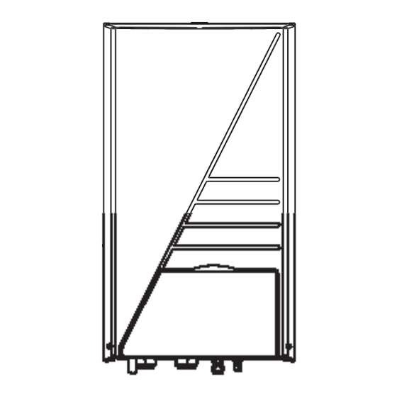
Page 8: Overview Of The Indoor Unit
VERVIEW OF THE INDOOR UNIT Outdoor unit Motorised 2-way valve for activation of the room Indoor unit thermostat (field supply) Heat exchanger Opening the indoor unit Pump FCU1..3 Fan coil unit with thermostat (field supply) Shut-off valve The front flap on the indoor unit cover gives access to the manometer and user interface. -
Page 9: Main Components
Air purge valve Remaining air in the water circuit will be automatically removed via the air purge valve. Backup heater The backup heater consists of an electrical heating element that will provide additional heating capacity to the water circuit if the heating capacity of the outdoor unit is insufficient due to low outdoor temperatures. -
Page 10: Switch Box Main Components
X13A socket Switch box main components The X13A socket receives the K3M connector (only for installations with domestic hot water tank). X9A socket The X9A socket receives the thermistor connector (only for installations with domestic hot water tank). Pump fuse FU2 (in line fuse) Pump relay K4M Transformer TR1 Solar/remote alarm address card (only for installations with solar... -
Page 11: Installation Of The Indoor Unit
NSTALLATION OF THE INDOOR UNIT Inspecting, handling and unpacking the unit The indoor unit is packed in a cardboard box, fixed by straps on Selecting an installation location a wooden pallet. At delivery, the unit must be checked and any damage must be The unit is to be wall mounted in an indoor location that meets the reported immediately to the carrier claims agent. -
Page 12: Mounting The Indoor Unit
Mounting the indoor unit Installation of the EKHBDP drain pan kit (only for EKHBX models) The weight of the indoor unit is approximately 55 kg. Two For heating/cooling models, it is necessary to install the drain pan kit persons are required to mount the unit. (see "Accessories"... - Page 13 Checking the water volume and expansion vessel pre- Example 1 pressure The indoor unit is installed 5 m below the highest point in the water circuit. The total water volume in the water circuit is 100 l. The unit is equipped with an expansion vessel of 10 litre which has a default pre-pressure of 1 bar.
-
Page 14: Charging Water
Overview Charging water The illustration below gives an overview of the required field wiring between several parts of the installation. Refer also to "Typical Connect the water supply to a drain and fill valve (see "Main application examples" on page components"... - Page 15 Internal wiring - Parts table Connection of the indoor unit power supply and communication cable Refer to the internal wiring diagram supplied with the unit (on the inside of the indoor unit switch box cover). The abbreviations used Power circuit and cable requirements are listed below.
- Page 16 Connection of the valve control cables Procedure Using the appropriate cable, connect the power circuit to the Valve requirements main circuit breaker as shown on the wiring diagram and the Power supply: 230 V AC illustration below. Maximum running current: 100 mA Connect the earth conductor (yellow/green) to the earthing Wiring the 2-way valve screw on the X1M terminal.
-
Page 17: Start-Up And Configuration
The following table summarizes the required configuration and TART UP AND CONFIGURATION thermostat wiring at the terminal block in the switch box. Pump operation is listed in the third column. The three last columns indicate The indoor unit should be configured by the installer to match the whether the following functionality is available on the user interface installation environment (outdoor climate, installed options, etc.) and (UI) or handled by the thermostat (T):... -
Page 18: Domestic Hot Water Tank Installation Configuration
Fuses or protection devices Domestic hot water tank installation configuration Check that the fuses or the locally installed protection devices are of the size and type specified in the chapter "Technical specifications" on page 25. Make sure that neither a fuse nor a When no domestic hot water tank is protection device has been bypassed. -
Page 19: Setting The Pump Speed
Press the z button for a minimum of 5 seconds to enter FIELD Setting the pump speed SET MODE. The $ icon (3) will be displayed. The current selected field The pump speed can be selected on the pump (see "Main setting code is indicated ;... - Page 20 [1-02] Set point at low ambient temperature (Lo_Ti): the [3] Auto restart target outgoing water temperature when the outdoor When power returns after a power supply failure, the auto restart temperature equals or drops below the low ambient function reapplies the user interface settings at the time of the power temperature (Lo_A).
- Page 21 [5-03] Space heating priority temperature: outdoor [7] Domestic hot water step length temperature below which the domestic water will be heated Applies only to installations with a domestic hot water tank. by the booster heater only, i.e. low outdoor temperature. When the domestic water is heated and the domestic hot water set [5-04] Set point correction for domestic hot water point temperature (as set by the user) has been reached, the booster...
- Page 22 [8] Domestic water heating mode timer NOTE Take care that [8-03] is always smaller than the Applies only to installations with a domestic hot water tank. maximum running time [8-01]. The 'domestic water heating mode timer' field settings defines the By adapting the booster heater delay time versus minimum and maximum domestic water heating times, and minimum the maximum running time, an optional balance...
-
Page 23: Field Settings Table
Field settings table Installer setting at variance with default value First Second Default code code Setting name Date Value Date Value value Range Step Unit User permission level User permission level — Weather dependent set point Low ambient temperature (Lo_A) –10 –20~5 °C... -
Page 24: Test Run And Final Check
EST RUN AND FINAL CHECK Final check The installer is obliged to verify correct operation of the indoor and Before switching on the unit, read following recommendations: outdoor unit after installation. When the complete installation and all necessary settings have been carried out, close all front panels of the unit and refit the indoor unit cover. -
Page 25: Troubleshooting
Symptom 2: The unit is turned on but the compressor is not starting ROUBLESHOOTING (space heating or domestic water heating) This section provides useful information for diagnosing and OSSIBLE CAUSES ORRECTIVE ACTION correcting certain troubles which may occur in the unit. The unit must start up out of its In case of low water temperature, the operation range (the water... -
Page 26: Error Codes
Symptom 7: Space heating capacity shortage at low outdoor Error codes temperatures OSSIBLE CAUSES ORRECTIVE ACTION When a safety device is activated, the user interface LED will be flashing, and an error code will be displayed. Backup heater operation is not Check that the "backup heater activated. - Page 27 Error Error code Failure cause Corrective action code Failure cause Corrective action Booster heater thermal protector Reset the thermal protector PCB failure Contact your local dealer. is open (applies only to Electric component failure Contact your local dealer. installations with a domestic hot water tank) Failure of capacity setting Contact your local dealer.
-
Page 28: Technical Specifications
ECHNICAL SPECIFICATIONS General Heating/cooling models (EKHBX) Heating only models (EKHBH) Nominal capacity • cooling Refer to the Technical Data Refer to the Technical Data • heating Dimensions H x W x D 922 x 502 x 361 922 x 502 x 361 Weight 55 kg 55 kg... - Page 29 NOTES NOTES...
- Page 30 4PW42457-1...
Need help?
Do you have a question about the EKNBH016AB and is the answer not in the manual?
Questions and answers