
Related Manuals for britech TH115-AF-GB-10

Summary of Contents for britech TH115-AF-GB-10
- Page 1 Owner’s Guide Guide du propriétaire Guía para el usuario TH115-AF-GB-10 Programmable thermostat Thermostat programmable Termostato programable...
- Page 2 Read and save these instructions. Veuillez lire le mode d’emploi et le conserver en lieu sûr. Estas instrucciones deben leerse y conservarse.
-
Page 3: Table Of Contents
Operating Manual 400-115-050-EFS Table of contents Overview Before you start ..........2 Default schedule (Energy Star settings) ...14 About your thermostat ........3 Modifying the schedule ........15 Quick reference to controls ........4 Quick reference to display........5 Operation Running the schedule (automatic mode) ..16 Installation Temporary override of schedule.......16 Installing the thermostat ........6... -
Page 4: Before You Start
Operating Manual 400-115-050-EFS Before you start Read the entire document CAUTION: • Installation must be carried out by an electrician and must comply with national and local electrical codes. • Use this thermostat only for resistive load. • Do NOT install the thermostat in an area where it can be exposed to water or rain. •... -
Page 5: About Your Thermostat
TH115-AF-GB-10 About your thermostat The TH115 programmable thermostat has three temperature control modes: A mode: controls the ambient air temperature F mode: controls the floor temperature using an external temperature sensor AF mode: controls the ambient air temperature maintains the floor temperature within desired limits using an external temperature sensor See page 9 on how to change the temperature control mode setting. -
Page 6: Quick Reference To Controls
Operating Manual 400-115-050-EFS Quick reference to controls On/Standby switch TEST light /button for ground fault protection (see page 18) Day button Hour button Preset temperature buttons Minutes button Program button Backlight button Program clear button Up/Down buttons Mode selection /program exit Place on Standby to cut power to the heater (e.g., in the summer). -
Page 7: Quick Reference To Display
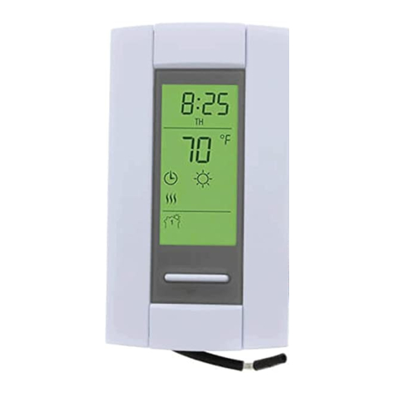
TH115-AF-GB-10 Quick reference to display Time Appears when the setpoint is displayed* Temperature* Mode Preset temperature icon (see page 13) Heating intensity indicator Temperature control mode (see page 3) Ground fault indicator (see page 18) Period * The thermostat normally displays the actual (measured) temperature. To view the setpoint, press either of the buttons once. -
Page 8: Installing The Thermostat
Operating Manual 400-115-050-EFS Installing the thermostat Faceplate Turn off power to the heating system at the service panel. Loosen the captive screw and remove the thermostat faceplate from the wallplate. (The screw remains captive and cannot be completely removed.) Connect the thermostat to the power supply and to the load (see page 7). Connect the floor sensor (see page 8). -
Page 9: Wiring Diagram
TH115-AF-GB-10 Wiring diagram NOTE: Connect the wires using the provided solderless connectors for copper wires: Power Power 120 V 240 V supply supply Black Black White Black Black Black Black Black Black White Load Load... -
Page 10: Floor Sensor / Remote Control Connections
Operating Manual 400-115-050-EFS Floor sensor / remote control connections Insert the floor sensor cable through one of the two openings on the wallplate and connect the sensor wires to terminals 1 and 2 (no polarity). • The sensor cable must pass outside the electrical box and follow the wall down to the floor. -
Page 11: Configuration Switches
TH115-AF-GB-10 Configuration switches Configuration switches are on the back of the faceplate. Factory settings are shown inside gray cells. Configurations Down Display format °F / 12 h °C / 24 h Enable Disable Early Start Temperature control mode Early Start can be used in Automatic mode only. When this function is enabled, the thermostat calculates the optimal time to start heating in order to obtain the desired temperature by the set time. -
Page 12: Clock And Day
Operating Manual 400-115-050-EFS Clock and day To set the clock and the day: Press the Hour button to set the hour. Press the Min button to set the minutes. Press the Day button to set the day. Press the Mode/Ret button to exit. -
Page 13: Daylight Saving Time
TH115-AF-GB-10 Daylight Savings Time When Daylight Savings Time function is enabled (On), the thermostat automatically switches to Daylight Savings Time on the second Sunday of March and to normal time on the first Sunday of November. NOTE: The function is disabled (default setting) when the clock loses its setting. -
Page 14: Floor Temperature Limits
Operating Manual 400-115-050-EFS Floor temperature limits (AF mode only) NOTE: To avoid damaging your floor, follow your floor supplier’s recommendations regarding floor tem- perature limits. The minimum and maximum floor temperature limits are 5.0°C (41°F) and 28.0°C (82°F) by default. To modify these limits, proceed as follows: Switch the thermostat to Standby. -
Page 15: Preset Temperatures
TH115-AF-GB-10 Preset temperatures The thermostat has 3 preset temperatures. The following table shows the intended use and the default setting of each of the preset temperatures. Preset temperature Intended use Displayed icon A/AF modes F mode Comfort When at home 21.0°C (70°F) -
Page 16: Default Schedule (Energy Star Settings)
Operating Manual 400-115-050-EFS Default schedule (Energy-Star settings) The schedule consists of 4 periods per day, which represents a typical work day. The Comfort ( ) preset temperature is automatically used in Periods 1 and 3 and the Economy ( ) preset temperature in Periods 2 and 4. -
Page 17: Modifying The Schedule
TH115-AF-GB-10 Modifying the schedule Press Pgm to access the programming mode. Period 1 is selected. Press Day to select the day to program (hold for 3 seconds to select the entire week). Press Hour and Min to set the start time of the selected period, or press Clear if you want to skip the period (--:-- is displayed). -
Page 18: Running The Schedule (Automatic Mode)
Operating Manual 400-115-050-EFS Running the schedule (automatic mode) In automatic mode, the thermostat follows the programmed schedule (see page 14). To place the thermostat in this mode, press Mode/Ret until is dis- played. Temporary override of schedule If you modify the setpoint temperature (by pressing the button) when the thermostat is in Automatic Mode, the new temperature will be used until the beginning of the next period. -
Page 19: Permanent Override (Manual Mode)
TH115-AF-GB-10 Permanent override of schedule (manual mode) In manual mode, the thermostat does not follow the programmed schedule. To place the thermostat in this mode, press Mode/Ret to display on the screen. Set the temperature using the button. When you go on vacation (vacation mode) In this mode, the thermostat uses the vacation preset temperature (see page 13). -
Page 20: Ground Fault Protection (Gfci)
Operating Manual 400-115-050-EFS Ground fault protection (GFCI) This ground fault protection thermostat is different from conventional thermostats. In the event of a ground fault, the ground fault protection mechanism on the thermostat will trip and quickly stop the flow of electricity to prevent serious injury. Definition of a ground fault Instead of following its normal safe path, electricity passes through a person’s body to reach the ground. - Page 21 TH115-AF-GB-10 Ground fault protection (con’d) Testing the ground fault protection To ensure the ground fault protection is always in working order, test it once the thermostat is installed and on a monthly basis thereafter. Increase the setpoint temperature above the measured temperature in order TEST button/light to activate the heating system.
-
Page 22: Error Messages
Operating Manual 400-115-050-EFS Error Messages The measured temperature is below the thermostat’s display range. Heating is activated. The measured temperature is above the thermostat’s display range. Heating is deactivated. Verify the thermostat connection and sensor connection. -
Page 23: Technical Specifications
TH115-AF-GB-10 Technical Specifications Maximum Load (resistive only) Supply Wiring Current Power 120 VAC, 60Hz 15 A 1800 W 4 wires, double pole 240 VAC, 60Hz 15 A 3600 W 4 wires, double pole Display range: 0°C to 70.0°C (32°F to 158°F) Ambient setpoint range (A/AF modes): 5.0°C to 30.0°C (40°F - 86°F) -
Page 24: Customer Assistance
Operating Manual 400-115-050-EFS Customer Assistance... -
Page 25: Warranty
TH115-AF-GB-10 Warranty... - Page 26 Operating Manual 400-115-050-EFS...
Need help?
Do you have a question about the TH115-AF-GB-10 and is the answer not in the manual?
Questions and answers