
Related Manuals for britech TH115-AF-GB-10

Summary of Contents for britech TH115-AF-GB-10
- Page 1 Owner’s Guide Guide du propriétaire Guía para el usuario TH115-AF-GB-10 Programmable thermostat Thermostat programmable Termostato programable...
- Page 2 Read and save these instructions. Veuillez lire le mode d’emploi et le conserver en lieu sûr. Estas instrucciones deben leerse y conservarse.
-
Page 3: Table Of Contents
Operating Manual 400-115-050-EFS Table of contents Overview Before you start ..........2 Default schedule (Energy Star settings) ...14 About your thermostat ........3 Modifying the schedule ........15 Quick reference to controls ........4 Quick reference to display........5 Operation Running the schedule (automatic mode) ..16 Installation Temporary override of schedule.......16 Installing the thermostat ........6... -
Page 4: Before You Start
Operating Manual 400-115-050-EFS Before you start Read the entire document CAUTION: • Installation must be carried out by an electrician and must comply with national and local electrical codes. • Use this thermostat only for resistive load. • Do NOT install the thermostat in an area where it can be exposed to water or rain. •... -
Page 5: About Your Thermostat
TH115-AF-GB-10 About your thermostat The TH115 programmable thermostat has three temperature control modes: A mode: controls the ambient air temperature F mode: controls the floor temperature using an external temperature sensor AF mode: controls the ambient air temperature maintains the floor temperature within desired limits using an external temperature sensor See page 9 on how to change the temperature control mode setting. -
Page 6: Quick Reference To Controls
Operating Manual 400-115-050-EFS Quick reference to controls On/Standby switch TEST light /button for ground fault protection (see page 18) Day button Hour button Preset temperature buttons Minutes button Program button Backlight button Program clear button Up/Down buttons Mode selection /program exit Place on Standby to cut power to the heater (e.g., in the summer). -
Page 7: Quick Reference To Display
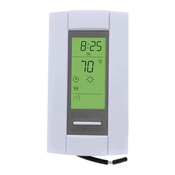
TH115-AF-GB-10 Quick reference to display Time Appears when the setpoint is displayed* Temperature* Mode Preset temperature icon (see page 13) Heating intensity indicator Temperature control mode (see page 3) Ground fault indicator (see page 18) Period * The thermostat normally displays the actual (measured) temperature. To view the setpoint, press either of the buttons once. -
Page 8: Installing The Thermostat
Operating Manual 400-115-050-EFS Installing the thermostat Faceplate Turn off power to the heating system at the service panel. Loosen the captive screw and remove the thermostat faceplate from the wallplate. (The screw remains captive and cannot be completely removed.) Connect the thermostat to the power supply and to the load (see page 7). Connect the floor sensor (see page 8). -
Page 9: Wiring Diagram
TH115-AF-GB-10 Wiring diagram NOTE: Connect the wires using the provided solderless connectors for copper wires: Power Power 120 V 240 V supply supply Black Black White Black Black Black Black Black Black White Load Load... -
Page 10: Floor Sensor / Remote Control Connections
Operating Manual 400-115-050-EFS Floor sensor / remote control connections Insert the floor sensor cable through one of the two openings on the wallplate and connect the sensor wires to terminals 1 and 2 (no polarity). • The sensor cable must pass outside the electrical box and follow the wall down to the floor.
Need help?
Do you have a question about the TH115-AF-GB-10 and is the answer not in the manual?
Questions and answers