Pioneer DEH-P646 Ser

Pioneer DEH-P646 Ser

Multi-cd control high power cd player with fm/am tuner

Advertisement

S
ervice
M anua l
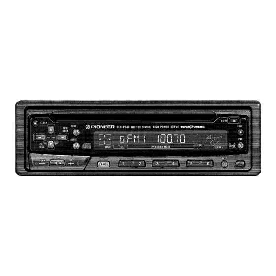
MULTI-CD CONTROL HIGH POWER CD PLAYER WITH FM/AM TUNER
DEH-P646
DEH-546
- See the separate manual CX-597(CRT1829) for the CD mechanism description, disassembly and circuit
description.
- The CD mechanism employed in this model is one of S7 series.
CONTENTS
1. SAFETY INFORMATION ............................................2
2. EXPLODED VIEWS AND PARTS LIST .......................3
3. SCHEMATIC DIAGRAM ...........................................10
4. PCB CONNECTION DIAGRAM ................................30
5. ELECTRICAL PARTS LIST ........................................40
6. ADJUSTMENT..........................................................50
PIONEER ELECTRONIC CORPORATION
PIONEER ELECTRONICS SERVICE INC.
PIONEER ELECTRONIC [EUROPE] N.V.
PIONEER ELECTRONICS ASIACENTRE PTE.LTD. 501 Orchard Road, #10-00, Lane Wheelock Place, Singapore 23880
C PIONEER ELECTRONIC CORPORATION 1998
DEH-P646
4-1, Meguro 1-Chome, Meguro-ku, Tokyo 153-8654, Japan
P.O.Box 1760, Long Beach, CA 90801-1760 U.S.A.
Haven 1087 Keetberglaan 1, 9120 Melsele, Belgium
ES
7. GENERAL INFORMATION .......................................56
7.1 PARTS .................................................................56
7.1.1 IC................................................................56
7.1.2 DISPLAY ....................................................62
7.2 DIAGNOSIS ........................................................63
7.2.1 DISASSEMBLY .........................................63
7.2.2 TEST MODE ..............................................64
7.3 BLOCK DIAGRAM ..............................................66
8. OPERATIONS AND SPECIFICATIONS.....................68
K-FEA. FEB. 1998 Printed in Japan
ORDER NO.
CRT2149
ES

Advertisement

Table of Contents
loading

Summary of Contents for Pioneer DEH-P646

  • Page 1: Table Of Contents

    P.O.Box 1760, Long Beach, CA 90801-1760 U.S.A. PIONEER ELECTRONIC [EUROPE] N.V. Haven 1087 Keetberglaan 1, 9120 Melsele, Belgium PIONEER ELECTRONICS ASIACENTRE PTE.LTD. 501 Orchard Road, #10-00, Lane Wheelock Place, Singapore 23880 C PIONEER ELECTRONIC CORPORATION 1998 K-FEA. FEB. 1998 Printed in Japan...
  • Page 2: Safety Information

    DEH-P646,546 - CD Player Service Precautions 2. During disassembly, be sure to turn the power off 1. For pickup unit(CXX1230) handling, please refer since an internal IC might be destroyed when a con- to"Disassembly"(CX-597 Service Manual CRT1829). nector is plugged or unplugged.
  • Page 3: Exploded Views And Parts List

    - Screws adjacent to ∇ mark on the product are used for disassembly. - PACKING SECTION PARTS LIST Mark No. Description Part No. Mark No. Description Part No. 1 Cord Assy(DEH-P646/ES) CDE5483 8 Protector CHP1767 Cord Assy(DEH-546/ES) CDE5484 9-1 Polyethylene Bag...
  • Page 4 DEH-P646,546 - Owner’s Manual Model Part No. Language DEH-P646/ES CRD2561 English, Spanish CRD2562 Portuguese, Arabic DEH-546/ES CRD2714 English, Spanish, Portuguese, Arabic - Installation Manual Model Part No. Language DEH-P646/ES CRD2563 English, Spanish, Portuguese, Arabic DEH-546/ES CRD2579 English, Spanish, Portuguese, Arabic...
  • Page 5 DEH-P646,546 2.2 EXTERIOR Fig. 3...
  • Page 6 DEH-P646,546 - EXTERIOR SECTION PARTS LIST (1) PARTS LIST Mark No. Description Part No. Mark No. Description Part No. 1 Screw ASZ26P055FUC 46 Insulator CNM4684 2 Screw ASZ26P080FMC 47 Heat Sink CNR1458 3 Screw BSZ26P050FMC 48 FM/AM Tuner Unit CWE1485...
  • Page 7 97 Transistor(Q951, 971) 2SD2396 98 Spacer CNM5875 99 Clamper See Contrast table(2) (2) CONTRAST TABLE DEH-P646/ES and DEH-546/ES are constructed same except for the following: Part No. Mark No. Symbol and Description DEH-P646/ES DEH-546/ES 6 Cord Assy CDE5185 Not used...
  • Page 8 DEH-P646,546 2.3 CD MECHANISM MODULE Fig. 4...
  • Page 9 DEH-P646,546 - CD MECHANISM MODULE SECTION PARTS LIST Mark No. Description Part No. Mark No. Description Part No. 1 Control Unit CWX2224 46 Connector(CN701) CKS2774 2 Pickup Unit(Service) CXX1230 47 Connector(CN801) CKS2196 3 Screw IMS26P035FMC 48 Spring CBH1832 4 Screw...
  • Page 10: Schematic Diagram

    DEH-P646,546 3. SCHEMATIC DIAGRAM 3.1 OVERALL CONNECTION DIAGRAM(GUIDE PAGE) Note: When ordering service parts, be sure to refer to “EXPLODED VIEWS AND PARTS LIST” or “ELECTRICAL PARTS LIST”. Large size SCH diagram Guide page Detailed page...
  • Page 11 DEH-P646,546 Fig. 5...
  • Page 12 DEH-P646,546...
  • Page 13 DEH-P646,546 Fig. 6...
  • Page 14 DEH-P646,546...
  • Page 15 DEH-P646,546 Fig. 7...
  • Page 16 DEH-P646,546 3.2 CD MECHANISM MODULE(GUIDE PAGE) Large size SCH diagram Guide page Detailed page 22/6R3 CXA8912 BA05SFP CXA8986 CXA8702...
  • Page 17 DEH-P646,546 Fig. 8...
  • Page 18 DEH-P646,546...
  • Page 19 DEH-P646,546 Fig. 9 D-a E...
  • Page 20 DEH-P646,546...
  • Page 21 DEH-P646,546 Fig. 10...
  • Page 22 DEH-P646,546 Note:1. The encircled numbers denote measuring pointes in the circuit diagram. 2. Reference voltage - Waveforms REFO:2.5V 1 RFO 1 CH1: RFO 1 CH1: RFO 0.5V/div. 0.5µs/div. 1V/div. 1V/div. 0.5ms/div. 0.5ms/div. 2 CH2: MIRR 2 CH2: MIRR Normal mode: play 5V/div.
  • Page 23 DEH-P646,546 8 CH1: TEY 0 SIN 8 CH1: TEY 0.2V/div. 0.5V/div. 0.5V/div. 0.1s/div. 20ms/div. 5ms/div. 9 CH2: TIN ! CH2: SD 0.2V/div. 0.5V/div. Normal mode: play Normal mode: Play (12cm) → REFO → REFO → REFO → → REFO REFO...
  • Page 24 DEH-P646,546 ( CH1: R OUT 6 CH1: FEY 8 CH1: TEY 0.2V/div. 1V/div. 0.2V/div. 0.2ms/div. 1ms/div. 1ms/div. ) CH2: L OUT 3 CH2: FIN 9 CH2: TIN 1V/div. 0.5V/div. 0.5V/div. Normal mode: Play (1kHz 0dB) Normal mode: During AGC Normal mode: During AGC →...
  • Page 25 DEH-P646,546...
  • Page 26 DEH-P646,546 3.3 FM/AM TUNER UNIT...
  • Page 27 DEH-P646,546 Fig. 11...
  • Page 28 DEH-P646,546 3.4 KEYBOARD PCB...
  • Page 29 DEH-P646,546 Fig. 12...
  • Page 30: Pcb Connection Diagram

    DEH-P646,546 4. PCB CONNECTION DIAGRAM 4.1 TUNER AMP UNIT NOTE FOR PCB DIAGRAMS TUNER AMP UNIT 1. The parts mounted on this PCB include all necessary parts for IP-BUSIN CORD ASSY ANT.IN several destination. For further information for respective destinations, be sure to check with the schematic dia- gram.
  • Page 31 DEH-P646,546 SIDE A CN701 Fig. 13...
  • Page 32 DEH-P646,546 TUNER AMP UNIT...
  • Page 33 DEH-P646,546 SIDE B Fig. 14...
  • Page 34 DEH-P646,546 4.2 FM/AM TUNER UNIT SIDE A Fig. 15...
  • Page 35 DEH-P646,546 SIDE B Fig. 16...
  • Page 36 DEH-P646,546 4.3 CD MECHANISM MODULE SIDE A Fig. 17...
  • Page 37 DEH-P646,546 SIDE B Fig. 18...
  • Page 38 DEH-P646,546 4.4 KEYBOARD PCB,SWITCH PCB SIDE A Fig. 19...
  • Page 39 DEH-P646,546 SIDE B Fig. 20...
  • Page 40: Electrical Parts List

    DEH-P646,546 5. ELECTRICAL PARTS LIST NOTES: - Parts whose parts numbers are omitted are subject to being not supplied. - The part numbers shown below indicate chip components. Chip Resistor RS1/_S___J,RS1/__S___J Chip Capacitor (except for CQS..) CKS.., CCS.., CSZS..=====Circuit Symbol and No.===Part Name Part No.
  • Page 41 CEJA100M16 CEJAR47M50 CCSRTH9R0D50 CCSRTH120J50 CEJAR33M50 CKSQYB473K16 CCSRCH471J50 CKSRYB333K16 CKSRYB103K25 CKSQYB473K16 CKSRYB103K25 CCSRCH471J50 CKSQYB472K50 CCSRCH5R0C50 Unit Number : CWM5622 Unit Name : Tuner Amp Unit(DEH-P646/ES) CKSQYB104K16 CCSRRH201J50 MISCELLANEOUS CKSRYB223K25 CKSRYB103K25 TA2050S CCSRCH470J50 CA0008AM SN761027DL CKSQYB223K25 TDA7386 CKSQYB104K16 M5282FP CKSRYB472K50 CEJA330M10 MC14052BF...
  • Page 42 DEH-P646,546 =====Circuit Symbol and No.===Part Name Part No. =====Circuit Symbol and No.===Part Name Part No. ------ ------------------------------------------ ------------------------- ------ ------------------------------------------ ------------------------- Transistor 2SC2412K RESISTORS Transistor 2SC2412K Transistor 2SC2412K RS1/10S620J Transistor 2SD1760F5 RS1/10S101J Transistor IMD2A RS1/10S101J RS1/10S222J Transistor DTA114EK RS1/10S122J Transistor...
  • Page 43 DEH-P646,546 =====Circuit Symbol and No.===Part Name Part No. =====Circuit Symbol and No.===Part Name Part No. ------ ------------------------------------------ ------------------------- ------ ------------------------------------------ ------------------------- RS1/10S0R0J RS1/10S132J RS1/10S0R0J RS1/10S822J RS1/10S330J RS2PMF100J RS1/10S222J RD1/4PU471J RS1/10S222J RS1/10S223J RS1/10S102J RS1/10S682J RS1/10S222J RS1/10S103J RS1/10S152J RS1/10S224J RS1/10S472J RS1/10S104J RS1/10S472J...
  • Page 44 DEH-P646,546 =====Circuit Symbol and No.===Part Name Part No. =====Circuit Symbol and No.===Part Name Part No. ------ ------------------------------------------ ------------------------- ------ ------------------------------------------ ------------------------- CAPACITORS CEJA1R0M50 CKSQYB473K25 CEJA1R0M50 CKSQYB473K16 CEJA1R0M50 CKSQYB103K50 CEJA1R0M50 CEJA100M16 CEJA1R0M50 CEJA100M16 CEJA100M16 CKSQYB103K50 CKSQYB104K25 CCSQCH150K50 CKSQYB473K25 CCSQCH150K50 CKSQYB473K25 CKSQYB103K50...
  • Page 45 DEH-P646,546 =====Circuit Symbol and No.===Part Name Part No. =====Circuit Symbol and No.===Part Name Part No. ------ ------------------------------------------ ------------------------- ------ ------------------------------------------ ------------------------- CKSQYB473K25 Ferri-Inductor LAU2R2K CKSQYB102K50 Ferri-Inductor LAU2R2K CEJA101M10 Inductor LAU100K Ferri-Inductor LAU2R2K Unit Number : CWM5630 Ferri-Inductor LAU2R2K Unit Name...
  • Page 46 DEH-P646,546 =====Circuit Symbol and No.===Part Name Part No. =====Circuit Symbol and No.===Part Name Part No. ------ ------------------------------------------ ------------------------- ------ ------------------------------------------ ------------------------- RS1/10S0R0J RS1/10S472J RS1/10S102J RS1/10S224J RS1/10S473J RS1/10S102J RS1/10S473J RS1/10S822J RS1/10S473J RD1/4PU221J RS1/10S473J RD1/4PU511J RS1/10S473J RS1/10S1R0J RS1/10S473J RD1/4PU331J RS1/10S473J RD1/4PU331J RS1/10S222J...
  • Page 47 DEH-P646,546 =====Circuit Symbol and No.===Part Name Part No. =====Circuit Symbol and No.===Part Name Part No. ------ ------------------------------------------ ------------------------- ------ ------------------------------------------ ------------------------- CKSQYB103K50 CL200IRX CKSQYB103K50 Ceramic Resonator 16.93MHz CSS1363 CKSQYB102K50 Switch(Home) CSN1028 CEJA220M10 Switch(Clamp) CSN1044 CKSQYB223K50 RESISTORS CKSQYB473K16 CEJA220M6R3 RS1/8S100J CKSQYB103K50...
  • Page 48 Consists of 1824 RS1/8S181J Keyboard PCB 1825 RS1/8S101J Switch PCB 1826 RS1/8S181J 1827 RS1/8S101J Unit Number : CWM5636 1828 RS1/8S121J Unit Name : Keyboard Unit(DEH-P646/ES) 1829 RS1/8S101J 1830 RS1/8S181J MISCELLANEOUS 1831 RS1/8S201J 1832 RS1/8S221J IC 1801 PD6197A IC 1802 RS-140 1833...
  • Page 49 DEH-P646,546 =====Circuit Symbol and No.===Part Name Part No. =====Circuit Symbol and No.===Part Name Part No. ------ ------------------------------------------ ------------------------- ------ ------------------------------------------ ------------------------- 1838 CL170PGCD CAPACITORS 1839 CL170PGCD 1840 CL170PGCD 1801 CKSQYB104K50 1841 CL170PGCD 1802 CEV100M16 1842 CL170PGCD 1803 CKSQYB104K25 1804 CKSQYB104K25...
  • Page 50: Adjustment

    DEH-P646,546 6. ADJUSTMENT 6.1 TUNER ADJUSTMENT - Connection Diagram BACK UP +14.4V DC Regulated Power Supply Lch + 4Ω Lch - mV Meter (1) Oscilloscope Rch + 4Ω Rch - Dummy Antenna Antenna Plug 50Ω(37.5Ω) Stereo FM SSG Modulator 50Ω(75Ω)
  • Page 51 DEH-P646,546 FM ADJUSTMENT Modulation M:MONO MOD., 400Hz 30%(22.5kHz Dev.) S:STEREO MOD., 1kHz, L or R=30%(20.25kHz+7.5kHz Dev.) NOTE:Before proceeding to further adjustments after switching power ON, let the tuner run for ten minutes to allow the circuits to stabilize. FM ADJUSTMENT...
  • Page 52 DEH-P646,546 6.2 CD SECTION 1)Precautions • Test mode cancellation • This unit uses a single power supply (+5V) for the reg- Switch ACC, back-up OFF. ulator. The signal reference potential, therefore, is connected to REFO(approx. 2.5V) instead of GND. • Disc detection during loading and eject operations is...
  • Page 53 DEH-P646,546 - Flow Chart Reset During regulator off,press the 6 key CD player select CDorSOURCE and the system will be put into the new test mode. ( Adjustment for T.OFFSET) ( Not adjustment for T.OFFSET) BAND 00 00'00" 99 99'99"...
  • Page 54: Checking The Grating After Changing The Pickup Unit

    DEH-P646,546 6.3 CHECKING THE GRATING AFTER CHANGING THE PICKUP UNIT • Note : Unlike previous CD mechanism modules the grating angle of the PU unit cannot be adjusted after the PU unit is changed. The PU unit in the CD mechanism module is adjusted on the production line to match the CD mecha- nism module and is thus the best adjusted PU unit for the CD mechanism module.
  • Page 55 DEH-P646,546 Ech → Xch 20mV/div, AC Grating waveform Fch → Ych 20mV/div, AC 0° 30° 45° 60° 75° 90°...
  • Page 56: General Information

    DEH-P646,546 7. GENERAL INFORMATION 7.1 PARTS 7.1.1 IC Pin Functions (UPD63702AGF) Pin No. Pin Name Function and Operation D.VDD Supplies current of positive voltage to the logic circuits System reset input pin Microcomputer interface AO="L": stb active and set to address register AO="H": stb active and set to parameter...
  • Page 57 DEH-P646,546 Pin No. Pin Name Function and Operation 52-54 C2D1-C2D3 Output pin for indicating the C2 error correction results D.VDD Supplies current of positive voltage to the logic circuit SFSY Outputs 1 word of the subcode. Generally, 1 cycle is approx 136 micro seconds SBSY The signal indicates the beginning of the subcode block.
  • Page 58 DEH-P646,546 PM2006A BA05SFP VREF 2 V CC 14kΩ BAND V REFP 35kΩ – VREF 2 V REF2 V CC X-GND LDET RE F CUR REQUEST DIVIDER PROGRAMABLE DIVIDER COUNTER DATA REGISTER MODE I/O-5 IN1 REG IN3 REG OUT2 CRESE T...
  • Page 59 DEH-P646,546 Pin Functions(PD4886A,PD4957A) Pin No. Pin Name Function and Operation swvdd Grille power supply control output dsens Grille detach sense input Not used isens Illumination sense input TESTIN Test program mode input 6-10 Not used reset Reset input Open Connect to VSS Crystal oscillator connection pin Crystal oscillator connection pin (12.582912MHz)
  • Page 60 DEH-P646,546 Pin No. Pin Name Function and Operation xrst CD LSI reset output xstb CD LSI strobe output VCAOUT Sub woofer volume control output SUBMUTE Sub woofer mute output TEST Test terminal Signal level input MODEL1 Model select input 76,77...
  • Page 61 DEH-P646,546 - Pin Functions (PD6197A) Pin No. Pin Name Function and Operation Crystal oscillator connection pin Crystal oscillator connection pin Not used MOD1,0 Connect to GND Not used KYDT Display/key data output DPDT Display/key data input REMIN Remote control pulse input...
  • Page 62: Display

    DEH-P646,546 7.1.2 DISPLAY - CAW1459 (DEH-P646/ES) - CAW1479 (DEH-546/ES) Fig. 22...
  • Page 63: Diagnosis

    DEH-P646,546 7.2 DIAGNOSIS 7.2.1 DISASSEMBLY - Removing the Case(Not shown) Removing the two screws. - Removing the Detach Grille Assy and CD Mechanism Module CD Mechanism 1. A×4 Module Connector Detach Grille Detach Button Fig. 23 Assy - Removing the Chassis Unit and Tuner Amp Unit 1.
  • Page 64: Test Mode

    DEH-P646,546 7.2.2 TEST MODE - Error Number Indication The system enters error mode to display the cause of error with a number when the system cannot operate CD or stops operation because of an error. The purpose of this measure is to reduce frequency of calls from users asking help for problems that are caused by incorrect operation by user, as well as to assist analysis and repair in servicing.
  • Page 65 DEH-P646,546 - New Test Mode When S-CD is specified as the source, basically the system plays as normal operation. After setup, the system dis- plays the cause and time (absolute time) of an error if focus search is improper, spindle lock is removed, subcode cannot be read, or sound is skipped.
  • Page 66: Block Diagram

    DEH-P646,546 7.3 BLOCK DIAGRAM - DEH-P646/ES...
  • Page 67 DEH-P646,546 Fig. 25...
  • Page 68: Operations And Specifications

    DEH-P646,546 8. OPERATIONS AND SPECIFICATIONS 8.1 OPERATIONS Fig. 26...
  • Page 69 DEH-P646,546...
  • Page 70 DEH-P646,546...
  • Page 71 DEH-P646,546...
  • Page 72 DEH-P646,546...
  • Page 73 DEH-P646,546...
  • Page 74 DEH-P646,546...
  • Page 75 DEH-P646,546...
  • Page 76 DEH-P646,546...
  • Page 77: Specifications

    DEH-P646,546 8.2 SPECIFICATIONS General FM tuner Power source ..14.4 V DC (10.8 – 15.1 V allowable) Frequency range ........87.5 – 108 MHz Grounding system ........Negative type Usable sensitivity ....11 dBf (1.0 µV/75 Ω, mono, S/N: 30 dB) Max.

This manual is also suitable for:

Deh-546

Table of Contents