Table of Contents
Advertisement
Quick Links
Advertisement
Table of Contents

Related Manuals for PNI RX5000


Summary of Contents for PNI RX5000
-
Page 2: Table Of Contents
TABLE OF CONTENTS IDENTIFYING THE PARTS OF THE RX5000....1 INSTALLING THE RX5000 ..........2-3 Mounting Guidelines.............2 Windshield Mounting ............2 Dashboard Mounting ............3 OPERATING THE RX5000 ..........4 Power On..............4 Modes and Operation ...........4 Mode Selection.............4 COMPASS OPERATION..........5-6 When to Calibrate............5 Calibrating the RX5000 ..........5 Compass Display............6... - Page 3 CONGRATULATIONS! You have acquired the RX5000 from PNI Corporation, the first radar/laser detector with a built-in digital compass. The RX5000 incorporates the same compass technology used in built-in com- passes for GM, Ford and Chrysler vehicles, to provide highly accurate and reliable compass readings in a radar/laser detector.
- Page 4 2-Amp Fuse Replacement -- fits inside the lighter socket adapter of the coiled 12V DC power cord. • Carrying Pouch -- for protection of your RX5000 during storage or travel. • Hard-Wire Kit -- for a more permanent installation of your RX5000 to your vehicle’s fuse panel (please seek...
-
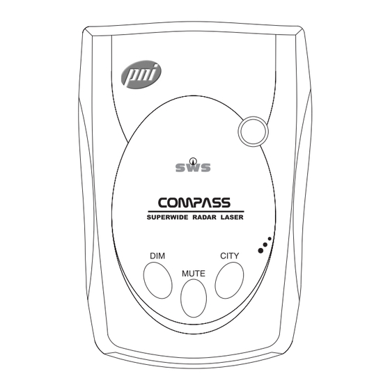
Page 5: Identifying The Parts Of The Rx5000
U.S. military bases. The use of any radar detection device is prohibited in commercial vehicles in all states by federal directive of February 1995. Outside of the United States, please check with local authorities regarding the use of the RX5000 before operating it. -
Page 6: Installing The Rx5000
INSTALLING THE RX5000 The RX5000 can be mounted on your windshield using the bracket provided, or on the dashboard using the hook and loop fastener strips. Mounting guidelines • Mount on the windshield or dashboard in a centered loca- tion that will not obstruct the view of the driver and is within reach so the buttons can be easily accessed. -
Page 7: Dashboard Mounting
INSTALLING THE RX5000 3. Slide the detector into its slot, located on the top back of the detector. 4. Bend the angle of the windshield mount- ing bracket, if neces- sary, to adjust for best DC12V viewing and detection angle. -
Page 8: Operating The Rx5000
OPERATING THE RX5000 Power On the RX5000 Turn the VOLUME/OFF thumb wheel control on. The RX5000 goes through a self-test pattern sequence and dis- plays the last mode previously set in memory. Modes and Operation The RX5000 has 3 operational modes: 1. -
Page 9: Compass Operation
COMPASS OPERATION The RX5000 must be calibrated for accurate heading infor- mation. Calibration allows the unit to separate the earth’s field from the magnetic fields generated by your vehicle. Before beginning calibration, the RX5000 must be installed in your vehicle in the location you wish to use it. -
Page 10: Compass Display
3 4 0 ° , etc.). 3 4 5 ° The RX5000 also detects when outside magnetic interfer- ence is compromising compass accuracy by flashing the . message. This may occur when driving D I S T O R T... -
Page 11: Radar Operation
Functions and Modes VOLUME/OFF Use the VOLUME/OFF thumb wheel located on the side of the RX5000 to turn the unit on or off, or to adjust volume level. DIM Mode Press the DIM button repeatedly less than 2 seconds each time to toggle between the four levels of brightness modes. -
Page 12: City Mode
(such as in vehicles over 10,000 lbs. or in Vir- ginia and Washington D.C.). The VG-2 interceptor works by detecting emissions gener- ated by a radar detector. When the RX5000 detects a VG-2 signal, it temporarily hides its own emissions and becomes invisible to the VG-2 interceptor. -
Page 13: Tutorial Mode
RADAR OPERATION Tutorial Mode The RX5000 has a Tutorial Mode intended to familiarize you with the various visual displays and distinct audible alerts the unit performs. To Begin the Tutorial Mode... 1. Turn the unit off with the VOLUME/OFF thumb wheel. -
Page 14: Detection Alerts
RADAR OPERATION Detection Alerts The RX5000 notifies you of the type of signal it receives (X, K, Ka, LASER, etc.) by using different audio and visual alerts for each signal. X, K, or Ka band Alerts When an X, K, or Ka band radar signal is detected, the... - Page 15 Presently, there are a few safety radar transmitters in use, and these alerts should be infrequent. As SWS™ trans- mitters increase by governmental agencies, expect more frequent safety alerts from your RX5000.
-
Page 16: Care And Maintenance
On hot days, the temperature inside your vehicle can reach levels that could damage your RX5000. Do not expose the RX5000 to rain, moisture, spray clean- • ers, or liquids that could damage the internal circuitry of the detector. -
Page 17: Troubleshooting
T U R N T W I C E You are holding the CITY button for longer than 3 sec- • onds in step 1 of calibration (see Calibrating the RX5000, page 5). Make sure you release the CITY button immedi- ately when you hear the unit beep. - Page 18 TROUBLESHOOTING The RX5000 did not alert when you passed an officer... • Not all police cars have radar/laser or it may not be in use at that time. • Make sure that you are in Dual Mode or Radar Mode (see page 4).
-
Page 19: Facts About Radar And Laser
FACTS ABOUT RADAR AND LASER Radar guns for speed enforcement have been used since the 1950’s when X band was introduced. Radar was developed in World War II and the word “RADAR” stands for RAdio Detec- tion And Ranging. K band followed and Ka band was developed in the 1980’s. -
Page 20: Driving Tips
DRIVING TIPS Radar and laser guns make mistakes! Approximately 20% of all Radar and Laser fines are issued in error, as radar and laser guns have limitations. For example, Radar looks for the most reflective target. You are obeying the speed limit but a larger vehicle close to you is speeding. -
Page 21: Specifications
SPECIFICATIONS Radar: Receiver Type: Dual Conversion Superheterodyne Antenna Type: Linear Polarized, Self Contained Detector Type: Scanning Frequency Discriminator Frequency Operation: X Band - 10.525 GHz +/- 50 MHz K Band - 24.150 GHz +/- 100 MHz Ka Band (Superwide) - 34.700 GHz +/- 1,300 MHz Safety Radar - 24.100 GHz Laser:... -
Page 22: Service And Replacement
SERVICE AND REPLACEMENT For fastest service, contact or return your RX5000 to the place of purchase. If you wish to return the unit for replacement or repair to PNI, please follow the following procedures: Obtain a Return Merchandise Authorization (RMA) number by contacting PNI: •... -
Page 23: Warranty Information
If the product is found by PNI to be defective and you have provided proof of purchase acceptable to PNI, PNI’s entire liability and your exclusive remedy for breach of... - Page 24 5464 Skylane Boulevard, Suite A Santa Rosa, CA 95403-1084 www.pnicorp.com Version F1-02-01...
Need help?
Do you have a question about the RX5000 and is the answer not in the manual?
Questions and answers