LG DLE5977W Service Manual
Electric & gas
Hide thumbs
Also See for DLE5977W:
- Owner's manual (64 pages) ,
- Service manual (45 pages) ,
- Specifications (2 pages)
Table of Contents
Advertisement
Advertisement
Table of Contents

Related Manuals for LG DLE5977W


Summary of Contents for LG DLE5977W
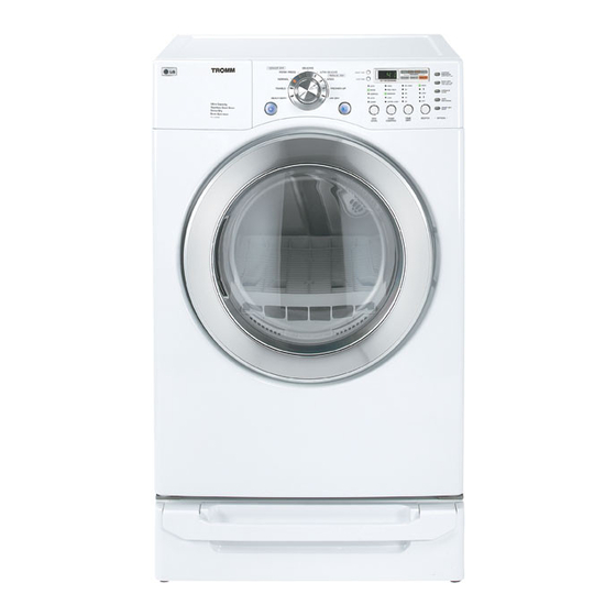
- Page 1 Website:http://www.LGservice.com [For U.S.A] www.lg.ca [For Canada] ELECTRIC & GAS DRYER SERVICE MANUAL CAUTION READ THIS MANUAL CAREFULLY TO DIAGNOSE TROUBLES CORRECTLY BEFORE OFFERING SERVICE. MODEL : DLE5977W/DLG5988W DLE5977B/DLG5988B DLE3777W/DLG3788W...
- Page 2 Feb. 2004 PRINTED IN KOREA P/No.:3828EL3005A...
-
Page 3: What To Do If You Smell Gas
IMPORTANT SAFETY NOTICE The information in this service guide is intended for use by individuals possessing adequate backgrounds of electrical, electronic, and mechanical experience. Any attempt to repair a major appliance may result in personal injury and property damage. The manufacturer or seller cannot be responsible for the interpretation of this information, nor can it assume any liability in connection with its use. -
Page 4: Table Of Contents
CONTENTS 1. SPECIFICATIONS ........................4 2. FEATURES AND BENEFITS ....................5 3. INSTALLATION INSTRUCTIONS ................... 6 4. DRYER CYCLE PROCESS ..................... 12 5. COMPONENT TESTING INFORMATION ................13 6. MOTOR DIAGRAM AND SCHEMATIC..................16 7. CONTROL LAY - OUT ......................17 8. WIRING DIAGRAM ......................18 9. -
Page 5: Specifications
SPECIFICATIONS DLE5977W DLE5977B DLE3777W REMARK ITEM DLG5988W DLG5988B DLG3788W Color Blue White Black Blue White Material & Top Plate Porcelain Painted Finishes Door Trim Chromate + STS Deco Blue White POWER SUPPLY 120V / 240V 60Hz (26A) MOTOR 250W (4.5A) -
Page 6: Features And Benefits
FEATURES AND BENEFITS DLE5977W/DLG5988W/DLE5977B/DLG5988B DLE3777W/DLG3788W... -
Page 7: Installation Instructions
INSTALLATION INSTRUCTIONS Review the following options to determine the appropriate electrical connection for your home: 3-wire receptacle 4-wire connection : Direct wire (NEMA type10-30R) Important : The places where a 4-wire connection is needed are , for example, mobile homes and areas Use the instructions at this section if your home has that local codes do not admit the use of 3-wire a 3-wire receptacle (NEMA type 10-30R) and you... -
Page 8: Wire Connection : Direct Wire
4. Put the hooked shape ends of the wire under the screw of the terminal block(hooked end facing rightward) and squeeze the hook together and screw tightly. 5. Put the hooked shaped ends of the other power supply cable wires under the outer terminal block screws(hooked end facing right) and squeeze the hooked ends together and screw tightly. - Page 9 Option 1: 3-Wire Connection with a Power Supply Cord lf your local codes or ordinances permit the connection of a frame-grounding conductor to the neutral wire, use these instructions. If your local codes or ordinances do not allow the connection of a frame-grounding conductor to the neutral wire, use the instructions under Section 3: Optional 3-wire connection.
- Page 10 Option 2: 4-wire connection with a Power supply cord. • lf your local codes or ordinances do not allow the use of a 3 wire connection, or you are installing your dryer in a mobile home, you must use a 4- wire connection.
- Page 11 Option 3: Optional 3-wire connection. • If your local codes or ordinances do not allow the connection of a frame-grounding conductor to the neutral wire, use the instructions under this section. 1. Remove center terminal block screw. 2. Remove appliance neutral ground wire (white) from external ground connector screw.
-
Page 12: Connect Gas Supply Pipe (Gas Dryer Only)
3-2. Connect Gas Supply Pipe (Gas Dryer ONLY) For further assistance, refer to section on Gas Requirements. 1. Make certain your dryer is equipped for use with the 3. Connect to gas supply pipe using a new flexible type of gas in your laundry room. Dryer is equipped stainless steel connector. -
Page 13: Dryer Cycle Process
DRYER CYCLE PROCESS Default Conditions of operation and termination Drying Cooling Wrinkle care Cycle Temp- Display erature time Electro- Temp- Default Temp- Level Time sensor Control time Control** 68 ± 4°C 47 ± 5°C HEAVY DUTY HIGH (Normal) 54min Saturation (5min) COTTON/ 66 ±... -
Page 14: Component Testing Information
COMPONENT TESTING INFORMATION When checking the Component, be sure to turn the power off, and do voltage discharge sufficiently. CAUTION Component Test Procedure Check result Remark 1. Thermal cut off Measure resistance of terminal If thermal fuse is open must •... - Page 15 Component Test Procedure Check result Remark 7. Heater Measure resistance of the • Electric type following terminal Terminal : 1 (COM) - 2 Resistance value : 10Ω Terminal : 1 (COM) - 3 Resistance value : 10Ω Terminal : 2 - 3 Resistance value : 20Ω...
- Page 16 Component Test Procedure Check result Remark 13. Outlet Thermostat Measure resistance of terminal • Gas type (Auto reset) to terminal • Gas funnel Open at 203 ± 7°F (95 ± 5°C) Resistance value ∞ Continuity < 1Ω Close at 158 ± 9°F (70 ± 5°C) •...
-
Page 17: Motor Diagram And Schematic
MOTOR DIAGRAM AND SCHEMATIC When checking Component, be sure to turn Power off, then do voltage discharge sufficiently. NOTE Contact On / Off by Centrifugal Switch STOP MODE RUN MODE (When Motor does not operate) (Motor operates) Centrifugal switch Centrifugal switch (Pull Drive forward) -
Page 18: Control Lay - Out
PWB ASSEMBLY DISPLAY LAY-OUT MODEL DISPLAY AS DIAGNOSTIC TEST OPTION PART MODEL P/No DISPLAY OP 1 OP 2 OP 3 OP 4 OP 5 OP 6 DLE5977W/B 18:FO 6871EC1115A DLG5988W/B 19:FO 6871EC1115B DLE3777W 18:F1 6871EC1115C DLG3788W 19:F1 6871EC1115D PWB ASSEMBLY LAY-OUT... -
Page 19: Wiring Diagram
WIRING DIAGRAM ELECTRIC DRYER WIRING DIAGRAM GAS DRYER WIRING DIAGRAM... -
Page 20: Diagnostic Test
DIAGNOSTIC TEST 1. This TEST should be used for Factory test /Service test. Do not use this DIAGNOSTIC TEST other than specified. 2. Activating the Heater manually with the Door open may trip the Thermostat attached to the Heater, therefore do not activate it manually. -
Page 21: Test 1 120Vac Electrical Supply
Test 1 120VAC Electrical supply When measuring power, be sure to wear insulated gloves, to and avoid an Caution electric shock. Trouble Symptom No power was applied to Controller. (LED, Display off) Measurement Condition With Dryer Power On; Connector linked to Controller. •... -
Page 22: Test 2 Thermistor Test
Test 2 Thermistor Test --- Measure with Power Off Before measuring resistance, be sure to turn Power off, and do voltage discharge. Caution (When discharging, contact the metal plug of Power cord with the Ground.) During Diagnostic Test, tE1 and tE2 Error occur. Trouble Symptom During operation, Heater would not turn off, or remains on. -
Page 23: Test 3 Motor Test
Test 3 Motor test Before measuring resistance, be sure to turn Power off, and do voltage discharge. Caution (When discharging, contact the metal plug of Power cord with earth line.) Trouble Symptom Drum will not rotate; No fan will function; No Heater will work. Measurement Condition Turn the Dryer’s Power Off, then measure resistance. -
Page 24: Test 4 Moisture Sensor
Test 4 Moisture sensor Before measuring resistance, be sure to turn Power off, and do voltage discharge. Caution (When discharging, contact the metal plug of Power cord with earth line.) Trouble Symptom Degree of dryness does not match with Dry Level. Measurement Condition Turn the Dryer’s Power Off, then measure resistance. -
Page 25: Test 5 Door Switch Test
Test 5 Door switch test Before measuring resistance, be sure to turn Power off, and do voltage discharge. Caution (When discharging, contact the metal plug of Power cord with earth line.) Door Opening is not sensed.(During operation, when opening Door, Drum motor and Trouble Symptom Heater run continuously;... -
Page 26: Test 6 Heater Switch Test - Electric Type
Test 6 Heater switch test - Electric Type Before measuring resistance, be sure to turn Power off, and do voltage discharge. Caution (When discharging, contact the metal plug of Power cord with earth line.) While operating, Heating will not work. Trouble Symptom Drying time takes longer. -
Page 27: Test 7 Gas Valve Test - Gas Type
Test 7 GAS Valve test - Gas Type Caution When measuring power, be sure to wear insulated gloves, to avoid electric shock. While operating, Heating will not work. Trouble Symptom Drying time takes longer. Measurement Condition With dryer power on Power On &... -
Page 28: Change Gas Setting (Natural Gas, Propane Gas)
CHANGE GAS SETTING (NATURAL GAS, PROPANE GAS) Warning After Natural Gas Setting, applying Propane Gas Orifice or wrong use of Natural Gas Orifice will result in fire. Conversion must be made by a qualified technician. Initially , Natural Gas mode is set. Propane Gas Orifice is on sale as a Service Part to authorized servicers only. - Page 29 GAS VALVE FLOW START KEY PUSH “VALVE 1” ON IGNITE ON IGNITE TEMPERATURE ABOUT 370”F FRAME DETECT OPEN IGNITE OFF “VALVE 2” ON GAS IGNITION FRAME DETECT CLOSE DRYING “VALVE 2” OFF GAS IGNITION GAS VALVE STRUCTURE START VALVE 1 IGNITER FRAME OPEN...
-
Page 30: Disassembly Instructions
DISASSEMBLY INSTRUCTIONS Disassemble and repair the unit only after pulling out power plug from the outlet. Remove 3 screws on the plate upper. Push the top plate Open the top plate... - Page 31 Remove 2 screw on the control panel frame. Disconnect the connectors. Pull the control panel assembly. Remove 9 screws on the PWB(PCB) assembly, display. Remove 4 screws on the PWB(PCB) assembly, main. Disassemble the control panel assembly.
- Page 32 Open the top plate. Open the control panel assembly. Open the door assembly. Remove 2 screws. Remove 4 screws from upper side. Disconnect the harness of door switch.
- Page 33 Open the top plate. Remove Cover Cabinet. Disconnect the door lamp and electro sensor connector. Remove 4 screws. Disassemble the Tub Drum [Front]. Open the top plate. Remove the Cover Cabinet and Tub drum [front]. Disengage belt from motor and idler pulleys. Carefully remove Drum out through front of dryer.
- Page 34 Remove screw & exhaust duct. PORTION “A” Detach and remove the bottom, left or right side knockout as desired. Reconnect the new duct[11 in(28cm)] to the DUCT blower housing, and attach the duct to the base. TAPE Pre-assemble 4" elbow with 4" duct. Wrap duct tape around joint.
- Page 35 Remove the filter. Remove 3 screws. Pull the grill. Disconnect electro sensor. Open the top plate. Remove the Cover Cabinet and Tub Drum [Front]. Remove the Drum assembly. Remove 2 screws and cover(Air guide). Remove the bolt and washer. Pull the fan. Disconnect the motor clamp and motor.
- Page 36 Open the top plate. Remove the Cover Cabinet. Remove filter and 2 screws. Pull the air duct towards the front. Open the top plate. Remove the Cover Cabinet and Tub Drum [Front]. Remove the Drum assembly and Tub Drum [Rear]. Disconnect Air duct from the Tub Drum [Front].
-
Page 37: Exploded View
EXPLODED VIEW 12-1. Control Panel & Plate Assembly A210 A130 A120 A110... -
Page 38: Cabinet & Door Assembly
12-2. Cabinet & Door Assembly A700 A800 A390 A330 A600 A500 A320 A310 A400 A410 A460... -
Page 39: Drum & Motor Assembly : Electric Type
12-3-1. Drum & Motor Assembly : Electric Type F200 K400 K120 K140 K100 K130 K250 K310 K330 K320 K340 K221 K210 K250 K550 K560 K610 K240 F140 K510 K520 K640 F130 F110 K650... -
Page 40: Drum & Motor Assembly : Gas Type
12-3-2. Drum & Motor Assembly : Gas type F200 K400 K120 K140 K100 K130 K250 K310 K330 K320 K340 K221 K210 K250 K550 K560 K610 K240 K510 K520 K640 M150 M240 M220 M160 K650 M171 M170 M210 M140 M230 M110 M190 M171 : Propane Gas orifice M180... -
Page 41: Replacement Parts List
¡Æ Note : S(Safety Parts), AL(Alternative parts) L G M O D E L : T D - V 10050E, TD- V 10051E MODEL P/N DESCRIPTION DLE5977W DLE3777W A500 CABINET ASSEMBLY 3091EL0003A... - Page 42 CAUTION : Before replacing any part of these components, read carefully the safety precautions in this manual. ¡Æ Note : S(Safety Parts), AL(Alternative parts) L G M O D E L : T D - V 10050G, TD- V 10051G MODEL P/N DESCRIPTION DLG5988W...
Need help?
Do you have a question about the DLE5977W and is the answer not in the manual?
Questions and answers