Table of Contents
Advertisement
Quick Links
Advertisement
Table of Contents

Related Manuals for IDX CW-7 Cam-Wave HD

Summary of Contents for IDX CW-7 Cam-Wave HD
- Page 1 CW-7 Operation Manual EU Version 2 Edition IDX Company, Ltd.
- Page 3 IDX thanks you for choosing the CW-7 and is sure that you will benefit from its unique features. Please read this instruction manual to safely operate and to maximize performance. The material contained in this manual consists of information that is the property of IDX Company, Ltd.
-
Page 4: Table Of Contents
Table of contents SAFETY INSTRUCTIONS ..............3 CONTENTS ................... 7 Product overview ................7 Switches and connectors ..............9 2.1. CW-7 TX ..................9 2.2. CW-7 RX ................... 11 LED indicators ................13 3.1. LED indicator functions ............13 3.2. CW-7 Link initialization ............ -
Page 5: Safety Instructions
It may cause fire or electric shock. the polarity of the connector is Please consult your dealer or local correct, as this will avoid smoke or IDX office for inspection and repair fire. services. ●Do not use this product near water or ●In case of damage, smoke, unusual... - Page 6 CAUTION - continued Fire or excessive heat may cause injury or damage to surroundings. ●If ventilation openings are blocked, ●After long periods of continuous this may cause excessive heat or use, the case of the unit may become damage. very heated – be cautious when touching.
- Page 7 CW-7 Important Notification of Use CAUTION IDX requires that CW-7 TX (transmitter) be installed on the V-Mount interface of a video camera. Depending on connectivity, installing CW-7 TX with equipment other than a video camera may cause problems to CW-7 TX or other equipment.
- Page 8 CW-7 Important Notification of Use CAUTION Please do not connect between DC-IN of CW-7 and DC-OUT of the camera while powering with battery as shown below. This may cause serious damages to the CW-7. Attention: When used EXT-DC and battery simultaneously ...
-
Page 9: Contents
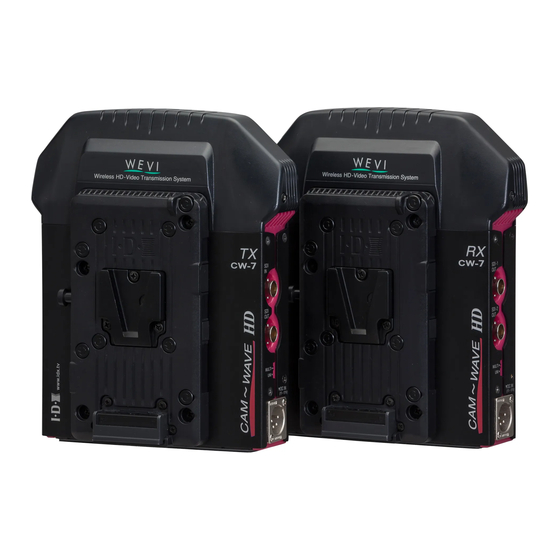
CONTENTS 1. Product overview The CW-7 is a wireless transmission device which transmits HD-SDI/SDI video and audio with 5GHz band radio frequencies. TX is the transmitter, and connects to a video source such as a video camera. RX is the receiver, and connects to a monitor, for example. - Page 10 Attention * The transmission distance may vary depending on frequencies, surroundings, radio wave conditions, buildings, weather condition etc. The transmission distance of 50m (150ft) is not definite. * When CW-7 is placed near a device such a TV, the transmitted video image may be disrupted.
-
Page 11: Switches And Connectors
2. Switches and connectors 2.1. CW-7 TX (Transmitter) ① ② ③ ④ ⑥ ⑤ 1. MODE STATUS LED Indicate selected power output mode. 2. LINK LED Indicate link status (Linked or Searching). 3. FREQ SELECT Select transmission frequencies. Manual selection : CH1 / CH2 Automatic selection : DFS AUTO INDOOR / DFS AUTO OUTDOOR... - Page 12 ⑪ ⑦ ⑧ ⑨ ⑩ ⑫ 7. SDI IN Connects the video source. 8. SDI OUT SDI Loop-thorough output. Use for video monitoring. 9. UNI/MULTI SW Select the link mode. UNI :Unicast mode MULTI :Multicast mode Use when external power is connected. 10.
- Page 13 2.2. CW-7 RX (Receiver) ① ② ⑤ ③ ④ 1. MODE STATUS LED Indicate level of incoming signal. 2. LINK LED Indicate link status (Linked or Searching). 3. FREQ SELECT Select frequency. Manual selection : CH1 / CH2 Automatic selection : DFS AUTO INDOOR / DFS AUTO OUTDOOR In DFS AUTO position, transmission frequency is selected automatically.
- Page 14 ⑥ ⑩ ⑦ ⑧ ⑨ ⑪ 6. SDI-1 OUT Connect to the monitor, recorder, etc. 7. SDI-2 OUT Buffered out of SDI-1 8. UNI/MULTI SW Select the link mode. UNI :Unicast mode MULTI :Multicast mode 9. DC-IN Use when external power is connected. ...
-
Page 15: Led Indicators
3. LED indicators 3.1. LED indicator functions MODE STATUS LED Indicates manually selected transmission output power mode (HIGH/LOW), and the UNICAST/MULTICAST setting. HIGH : Two lights on. LOW : One light on. UNICAST : LED lights Green. ... -
Page 16: Link Initialization
3.2. CW-7 Link initialization When the power switch is turned on, TX and RX will start searching for a frequency that it can be linked to. It will change the link mode if it is in operation or the transmission signal is lost. The three LED lights will cycle ON and OFF, starting from bottom to top until it is firmly linked. -
Page 17: Selecting Frequencies And Power Output
4. Selecting frequencies and power output FREQ SELECT switch is equipped on both TX and RX. POWER MODE switch is located on TX side only. FREQ SELECT switch is used to select transmission and receiving frequency. FREQ SELECT switch must be same position on both TX and RX. POWER MODE switch enables you to change the transmission power, HIGH or LOW. -
Page 18: Dfs Function
4.2. DFS function When the FREQ SELECT switch selects DFS AUTO, DFS (Dynamic Frequency Selection) function will be enabled. If DFS detects radio waves of weather radar (using 5GHz band) the system will automatically search other available frequency band to avoid interference. The DFS function is regulated by the radio standard for use the frequencies of 5250-5300MHz and 5470-5725MHz. -
Page 19: Link Mode -Unicast/Multicast
5. Link mode -UNICAST/MULTICAST UNI/MULTI switch is used to select the link mode. UNI/MULTI select switch is located on both TX and RX and must be set in the same mode. 5.1. UNICAST mode (1 to 1 communication) When UNI/MULTI switch is set to UNI position, CW-7 links in UNICAST mode. -
Page 20: Multicast Mode (1 To N Communication)
5.2. MULTICAST mode (1 to n communication) When UNI/MULTI switch is set to MULTI position, the CW-7 links in MULTICAST mode. In MULTICAST mode, the transmitted video and audio can be received by multiple RX. Please note that if MULTICAST mode had been selected, there is no AES encryption. -
Page 21: Operation Guide
Please obtain each of the following items as needed for your specific application before use. BNC cable for HD-SDI IN and OUT. IDX ENDURA batteries or external power supply Note: Power supply; Use only an AC adaptor or batteries specified below. -
Page 22: When Signal Reception Is Unstable
6.3. When signal reception is unstable Unstable signal reception may be caused by the placement, such as position, height and angle of TX and RX or the operating environment. When TX and RX are placed too close to each other, the transmission signal may become too strong and may disturb the video signal. -
Page 23: Important Notice
TX and RX is 3m or less. CW-7 has a built-in antenna and modification of adding external antenna is not authorized by IDX. This may affect the performance of CW-7 and void IDX standard warranty. SDI signal complies with SMPTE-292M/SMPTE-259M however, clock jitter may exceed the regulated values caused by link condition. -
Page 24: Specifications
III. Specifications 8. CW-7 TX Video・Audio Video input signal SD-SDI(SMPTE 259M-C) HD-SDI(SMPTE 292M) Audio input signal SDI Embedded (Embedded Audio CH1,CH) Monitoring SD-SDI/HD-SDI through out Video Format HD: 4:2:2 YCbCr 10bit 1080/59.94i, 1080/50i, 1080/29.97p, 1080/25p, 1080/24p, 1080/23.98p, 1080/30PsF, 1080/29.97PsF, 1080/25PsF, 1080/24PsF, 1080/23.98PsF, 720/59.94p, 720/50p SD: 4:2:2 YCbCr 10bit... - Page 25 Power Power input Battery input: 11-17V / Ext-DC input: 11-17V Power output Through-out the DC power (Battery or Ext-DC) Recommended battery IDX ENDURA series Lithium Ion battery In and Out terminal Video input BNC ×1 (SD-SDI/HD-SDI) Video out BNC ×1 (SD-SDI/HD-SDI・Loop through out)
- Page 26 9. CW-7 RX Video・Audio Video output signal SD-SDI(SMPTE 259M-C) HD-SDI(SMPTE 292M) BNC x2 (Buffered output) Audio output signal SDI Embedded (Embedded Audio CH1,CH2) Video format HD: 4:2:2 YCbCr 10bit 1080/59.94i, 1080/50i, 1080/29.97p, 1080/25p, 1080/24p, 1080/23.98p, 1080/30PsF, 1080/29.97PsF, 1080/25PsF, 1080/24PsF, 1080/23.98PsF, 720/59.94p, 720/50p SD: 4:2:2 YCbCr 10bit 525i/59.94, 625i/50...
- Page 27 Power Power input Battery input: 11-17V / Ext-DC input: 11-17V Power output Through-out the DC power (Battery or Ext-DC) Recommended battery IDX ENDURA series Lithium Ion battery In and Out terminal Video input BNC ×2 (SD-SDI/HD-SDI・buffered out) Battery input V-Mount ×1...
-
Page 28: Warranty & Service
Physicall damages caused by dropping or vibration Malfunction/damage due to water immersion Unauthorized used and/or modification done by customer When any assistance is required, please contact your IDX dealer or appropriate IDX office below. Contact us IDX Technology Europe, Ltd. - Page 29 FOR SALES AND SERVICE CONTACT In Japan / Asia In the United States In Europe / Middle East. IDX Company, Ltd. IDX System Technology, Inc. IDX Technology Europe Ltd. 6-28-11 Shukugawara, Tama-Ku, 19001 Harborgate Way, Unit 9, Langley Park, Kawasaki-Shi, Kanagawa-Ken...
Need help?
Do you have a question about the CW-7 Cam-Wave HD and is the answer not in the manual?
Questions and answers