
Related Manuals for Chungho Super Iguassu ICE 900


Summary of Contents for Chungho Super Iguassu ICE 900
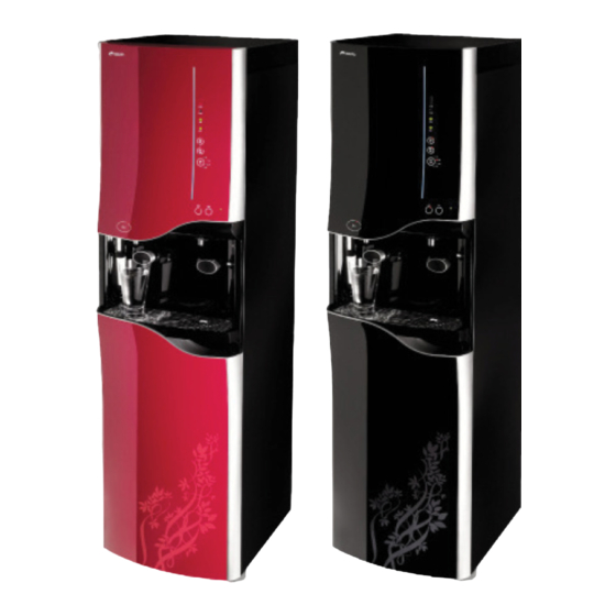
- Page 1 Technical & Repair guide for ChungHo Super Iguassu ICE 900 IGUASSU ICE 900 Technical Manual call 888.758.1234 for further technical support...
-
Page 2: Table Of Contents
Table of Contents 1. Designation of Components page 3 2. Product Features page 4-6 3. Exploded Diagram & Parts List page 7-12 3-1. Overall Exploded Diagram 3-2. Ice Making Department 3-3. Detailed Exploded Diagram (1) 3-4. Detailed Exploded Diagram (2) 3-5. -
Page 3: Designation Of Components
Designation of Components USB Port Light Detection Sensor Ice Full LED Water Full LED Hot Water/Ice Lock Button Hot/Econo Button Continuous Dispensing Mode Button Hot Water Selecting Button Cold Water Selecting Button Ambi Water Selecting Button Ice Dispensing Button Water Dispensing Nozzle Power Cord Water Dispensing Push Button Ice Dispensing Hole... -
Page 4: Product Features
(Patent application: No.2005-99663, 2005-365293, 200510127096.9, 11/342,117) 24 Hour Natural Water Circulation System (N.W.P.W.) ChungHo purification systems are designed to allow water to continuously flow for 24 hours within the water purifier by adopting a natural circulation method. This mode, called N.W.P.W. applies the natural weight of water pressure in order to supply clean and fresh water at all times. - Page 5 Infrared Water Level Detection Sensor Infrared OLC sensor is applied in IGUASSU ICE 500. It provides more improved detection accuracy than traditional mechanical detection types, thus allowing stable water level detection. The signal is connected to a controller in order to automatically adjust purified water levels. (Patent: No.426182) Safety Function (Ice Dispensing &...
- Page 6 Noise Prevention Operating noise level is significantly lowered due to applying a dual noise prevention material, and utilizing a shock mitigation structure at ice storage house, etc. System Display Functions and Safety Reinforcement The safety features of the product have been enhanced in order to prevent various problems. The system will inform the user(s) of abnormal occurrences through a flashing display icon and by automatically stopping the ice making function, cold water function, and water purification function when an abnormality in the system is detected.
-
Page 7: Exploded Diagram & Parts List
Exploded Diagram & Parts List 3-1 OVERALL DIAgRAM Water Dispensing Solenoid Valve Drainage Valve Drainage Switch... -
Page 8: Ice Making Department
3-2 ICE MAKINg DEPARTMENT Ice Full Sensor (RX) Sub Tank Inlet Solenoid Valve Ice Full Sensor (TX) Synchronous Motor (Camshaft) Cold Water Temperature Sensor Dischsrge Ass’y Cold Water Level Sensor Circulation Pump... -
Page 9: Detailed Exploded Diagram
3-3 DETAILED ExPLODED DIAgRAM (1) - Page 10 3-4 DETAILED ExPLODED DIAgRAM (2)
-
Page 11: Detailed Exploded Diagram
3-5 DETAILED ExPLODED DIAgRAM (3) -
Page 12: Parts List
3-6 PARTS LIST ABS+Acryl 65% Ambient Tank ABS+Acryl 65% Cover-Ambient Tank Drip Tray Stabilizer ICE FULL Sensor CASE (R) Grill - Drip Tray O-RING Circulation Pump HEAD Cold tank Ice making Unit EPS Manifold (oval) Cold/Hot Separate Drip Tray Motor S/W Panel FAUCET DECO-Cold/Hot Separate Dispensing Button Ice Releasing GUIDE COVER (bottom) -
Page 13: System Diagram
System Diagram 4-1 WATER PURIFICATION PROCEDURE Level Sensor Ambient Water Tank Ice Making Unit Ambient Water Sol. V/V Ice Making Water Cold Water Tank Cold Water Sol. V/V Pump Dispensing Cold Water Sol. V/V Ice Storaging Auto Hot Water Sol. V/V Unit Shutoff Valve... -
Page 14: Distribution Line Diagram
Distribution Line Diagram Ice detection Sensor Cold water temp. Sensor Switch Location detect drip tray Ice making temp. Sensor Drain Switch Dispensing Button Environmental temp. Sensor... -
Page 15: Product Specification
Product Specification Model Name Super Iguassu Ice (CHP-5070S) Type Tri-Temp POU Cooler w/ built-in Ice Maker 16.9W x 19.4D x 58.7H (inch) Dimension AC 110V/60Hz Rated Voltage Rated 720W (Hot Water + Ice Making) Consumed Power Power Consumption Hot/Cold 500W / 200W Water 220W Ice Making... -
Page 16: Installation Precautions
Installation Precautions When installing the product, do not install it at the following places. - Near fire - Near flammable material - Wet place - A place exposed to rain and snow - A place exposed to direct sunshine - Near chemicals (volatile material, organic solvent, etc.) - A place below 32°F or a place with the possibility of dropping below 32°F When the product is installed in a dark place, and the power saving function is set, then hot water system may not operate even during daytime. -
Page 17: Relocation/Installation Precautions
Relocation/Installation Precautions In case the product is needed to be transported, please make sure there is no water left at all inside of the unit before moving the product. (If the product is moved without the complete drainage process as described below, it may cause serious damage to the product.) This is to be performed with the power plug inserted. -
Page 18: Installation
Installation Install the product on a level surface. (Change product level using the product leg adjustment and confirm the level surface a level.) Close off the water supply valve as supplied to each household. Then tempo- rarily remove the connector part as provided from your given water source. Then connect the main water line adaptor. -
Page 19: Usage
Usage 10-1 DISPLAY (A) USB connection can be used to connect diagnostic testing device or to charge USB USB Port compatible electronic devices. (Note: Do not charge more than 30 minutes.) Detects amount of light around the unit, Light Detection Sensor thus enabling auto ON/OFF for hot water. -
Page 20: Operational Beep
Usage 10-3 OPERATIONAL BEEP Action Beep Remarks / Occurrence Action Beep Remarks / Occurrence During Power ON Ding Dong Dang One Time During Power ON Ding Dong Dang One Time During Key Input Ding~ One Time During Key Input Ding~ One Time During Hot Water Lock Ding Ding Ding... - Page 21 Ice Making Function Setting Touch CONST button for over 10 seconds. *As pressing the button, continuous water dispenser function is automatically set after LOCK 2seconds and Ice making function setting operates in 10 seconds. Continuous water dispenser function automatically is released after 5 seconds. ICE LED (Red) is turned on as the ice making function is set.
- Page 22 ECONO(power saving) Function Setting Touch the HOT/ECONO(hot water operation/power saving selection) touch ECONO sensor button. Touch HOT: ON Touch ECONO: OFF Power saving display LED is turned on and power saving function is set. * Power saving function is automatically set to turn on/off the hot water system through operation of light sensor detection in accordance to the brightness around the product while hot water function is set.
-
Page 23: Ice And Water Dispensing
10-5 ICE AND WATER DISPENSINg It enables to dispense Ice and Hot water when the Lock function is released. * If Lock function (of Ice and Hot water dispensing) is set, Ice dispensing and Hot water selection touch button do not function. -
Page 24: Understanding The Ice Making Process And Operation
10-6 UNDERSTANDINg THE ICE MAKINg PROCESS AND OPERATION The ice making system of the IGUASSU ICE 500 automatically operates according to designed program settings after applying power to the product. If power is supplied to the product by inserting the power plug, then ice making automatically operates without any manual setting. -
Page 25: Examination/Repair Procedure
Examination/Repair Procedure Malfunction Page 1 Power 2 Refrigerant Leak 3 Hot Gas Leak 4 Filtration Malfunction 5 Inlet Sol V/V Defect 6 Cold/Ambi/Hot Water Sol V/V Defect 7 Product Level Defect 8 Drainage 9 Hot Water Part Malfunction 10 Circulation Pump Defect 11 Tray Motor Coupler 12 Micro Switch Ass'y - Synchronous Motor 13 Cold Water Level Sensor Defect... -
Page 26: Power
12-1 POWER Power plug is inserted into a wall outlet but no LED lights. * Caution: Never touch electrical parts with wet hands How to Diagnose Open the Front Lower Panel to find the fuse holder. Check the Fuse location, and see if the Fuse (inside the Fuse holder) is open. -
Page 27: Refrigerant Leak
12-2 REFRIgERANT LEAK If malfunction causes by leak or clogging of coolant, > Send to ChungHo Repair Center How to Diagnose Touch the back grill with your hand to Coolant leak occurs at welding areas determine temp. (During Ice Making as marked below, check with the 100ºF ~ 140ºF : Hot) -
Page 28: Hot Gas Leak
12-3 HOT gAS LEAK Hot gas leaks cause under performance in ice making and/or cold water making process. > Send to ChungHo Repair Center Hot gas sol v/v: DC24V Coil (including Wire) + Body (mesh) Drain Outlet When hot gas leaks due to foreign objects in hot gas sol v/v, EVA temperature goes up, thus no ice or thin ice will be made. -
Page 29: Filtration Malfunction
12-4 FILTRATION MALFUNCTION Symptom Water tanks do not get full. How to Diagnose Check to see if Ambient tank is (25%) If clogged, it will prevent water flow. full. (OLC Mesh / Medium Filter) Check to see if water is flowing after the Post Carbon Filter. -
Page 30: Inlet Sol V/V Defect
12-5 INLET SOL V/V DEFECT Faulty inlet solenoid Valve causes water dispensing malfunction due to not supplying water to the cold water tank. Check inlet solenoid valves located at the bottm of Controller PCB. - Check its voltage is DC24V supplies to Sol V/V at terminal when dispensing. -
Page 31: Cold/Ambi/Hot Water Sol V/V Defect
12-6 COLD/AMBI/HOT WATER SOL V/V DEFECT Faulty water dispensing solenoid Valve (Hot/Cold/Ambient) causes water dispensing malfunction. Ambient Open front upper panel to check hot/cold/ambient water dispensing solenoid valves. - Check its voltage is DC24V supplies to Sol V/V at terminal when dispensing. Cold >... -
Page 32: Product Level Defect
12-7 PRODUCT LEVEL DEFECT If the product is not properly leveled, it may cause ice to over freeze and/or freeze irregularly. Check the product’s level by using a level detector which is located under the drip tray. Set the level accordingly. (Water leak may occur if the product is not leveled by more than 3 degree.) -
Page 33: Drainage
12-8 DRAINAgE Water may flow over to drip tray if the drain is not working properly. Water goes out to drainage outlet, - When water dispensed, water goes out through drip tray - When Ice melts from the storage - When cold tank overflows - When ambient tank overflows Check the connection if it’s bent or twisted. -
Page 34: Hot Water Part Malfunction
12-9 HOT WATER MALFUNCTION If hot water overheated, ambient tank’s temperature goes up then it could causes overflow. Check electric resistance of hot water temp-sensor and manual bimetal. Hot water temp-sensor : Check electric resistance. Auto Bimetal : 90N (Max 199.4°F) Manual Bimetal : 105N (when Off, 221°F) Check if bimetals are affixed properly onto hot water tank’s surface. -
Page 35: Circulation Pump Defect
12-10 CIRCULATION PUMP DEFECT Check leak/noise/voltage of the Circulation pump. Open the Front upper cover to check the circulation pump located at the bottom right. - Voltage check: AC220V/60Hz * Empty the cold tank before detaching the circulation pump from the body. - Detach Inlet Sol V/V - Drain all cold water by dispensing it. -
Page 36: Tray Motor Coupler
12-11 TRAY MOTOR COUPLER Tray motor coupler may be broken due to bridge-shaped ice, circulation pump defect, and ice rejection malfunction. Open Front upper panel to check the Synchronous Motor. Applied volatage : AC220V/60Hz Detach the motor to check breakage of motor coupler. -
Page 37: Micro Switch Ass'y - Synchronous Motor
12-12 MICRO SWITCH ASS’Y - SYNCHRONOUS MOTOR Defects on Micro Switch Ass’y of the Synchronous Motor cause malfunction on ice making and cold water making process. Open Front upper panel to check the switch of Synchronous Motor. (located inside EPS) (Micro Switch 2EA) Check the lever and connections of the drip tray motor. -
Page 38: Cold Water Level Sensor Defect
12-13 COLD WATER LEVEL SENSOR DEFECT Defects on cold level sensor cause either not supplying or over-supplying water to cold tank. > Replace it if faulty. Check cold water level sensor by opening the front upper cover. - If cold tank is overflowing by over-supplying, check after replacing the cold level sensor. -
Page 39: Display Module Defect
12-14 DISPLAY MODULE DEFECT Display or touch button may not work due to poor connections and PCB assembly. Function PCB - Check wires and connections - Check the sponge inside - Check for humidity inside Dispensing PCB - Check for residual water and remove if any - Check if the PCB is affixed tight Ice discharging PCB - Check for residual water and remove if any... -
Page 40: Cold Water Sensor Defect
12-15 COLD WATER SENSOR DEFECT Faulty cold water temperature sensor cause malfunction of cold water and ice making. - When open: reconnect it if disconnected, and replace the sensor if defected. - When short: Replace the sensor Check the cold water sensor by opening front upper panel. -
Page 41: Ice Full Sensor(Tx, Rx) Defect
12-16 ICE FULL SENSOR (Tx, Rx) DEFECT When displays Ice Full led on when it is not, or not display Ice Full led when when it is full. > Replace the sensor if faulty. Open the front upper panel to find the Transmitting Sensor(Tx) at the bottom left of the water tank, and open the rear panel to find the Receiving Sensor(Rx) at the bottom right of the water tank. -
Page 42: Ice Full Led Defect
12-17 ICE FULL LED DEFECT Open front upper panel to find the switch inside the Synchronous Motor. (inside EPS) - Ice Full LED Blinking : exceeding detection time (60 sec) - Ice Full LED Blinking : S/W pressed simultaneously (60 sec) - Ice Full LED blinking : when environmental sensor is faulty - Ice Full LED blinking :... -
Page 43: Pcb Controller
12-18 PCB CONTROLLER Unscrew bolts from the top cover and the rear panel (2EA). Unscrew bolts from the side panels. (2ea) Disconnect wires on the front upper panel from the Main PCB controller. Black... - Page 44 12-18 PCB CONTROLLER (CONT’D) PCB Cover after front upper panel detached. (2 screws need to be unscrewed to detach PCB cover) Detach PCB cover. Disconnect all wires connected to Main PCB Controller. Press PCB holder (5ea) to detach it from PCB control panel.
-
Page 45: Function Selection Pcb
12-19 FUNCTION SELECTION PCB Detach top cover (2 screws), and front upper panel (2 screws). Remove the screws : M3x8 (6EA) first on Function Selection PCB of the front upper panel. Detach Function Selection PCB carefully. - Page 46 12-19 FUNCTION SELECTION PCB (CONT’D) Disconnect wire between Function Selection PCB and Dispensing PCB. Unscrew the screws: M3x6 (2EA) that hold USB port from the Function selection PCB. Unscrew the screws: M3x6 (4EA) that hold the Function selection PCB.
- Page 47 12-19 FUNCTION SELECTION PCB (CONT’D) Disconnect wire between Function selection PCB and USB port. Disconnect all wires from the function selection PCB and replace it.
-
Page 48: Tray Motor/Micro Sw Change
12-20 TRAY MOTOR/MICRO SW CHANgE Detach Top Cover and Front upper panel. Remove or replace Rotating drip tray motor. Detach Cold water inlet Sol V/V. Detach EPS Motor panel and replace micro S/W. -
Page 49: Circulation Pump/Cold Temp Sensor Change
12-21 CIRCULATION PUMP/COLD TEMP SENSOR CHANgE Remove Top cover & Front upper panel. Detach Cold, Ambient, and Hot water sol V/V, and detach Cold Sol Inlet Silicon, Ambient Sol inlet silicon. Detach Hot, Ambi, Cold Sol Ass’y and EPS. Replace circulation pump, cold water temperature sensor, and/or cold water level sensor. -
Page 50: Sensor Table
12-23 SENSOR TABLE 12-23-A. ICE MAKINg TEMP SENSOR, COLD WATER TEMP SENSOR TABLE (°F) (KΩ) (°F) (KΩ) (°F) (KΩ) 22.2 18.1 14.7 12.1 43.3 34.5 27.6 12-23-B. ENVIRONMENT SENSOR TABLE (°F) (KΩ) (°F) (KΩ) (°F) (KΩ) 26.6 99.5 21.8 78.5 62.5 14.9 12.4... -
Page 51: Flow Charts
Flow Charts 13-1 MAIN FLOW CHART FULL LED water level Ice Making/Cold, Hot, blinking & Ambi Water Stop over? Level check subroutine Hot water subroutine COMP 5 min delay Discharging ice subroutine Operation Abnormal? Cold tank Inlet Sol V/V ON Full? Inlet Sol V/V OFF Ice Full... - Page 52 13-2 ICE FULL SUBROUTINE Ice making OFF? 5 cont’d Just For 7 Seconds Power on? TX Transnsmitting (PWM) Ice Full? Ice just ejected? Ice just dispensed? Normal Cold- Insulated operation (outside temp.) Comp ON / OFF After 10 min, Ice Full every 10 min.
- Page 53 13-3 HOT WATER SUBROUTINE 13-4 ICE EjECTION SUBROUTINE START START “ECONO” button Water Tray moves into Ice ejection position Night Time? Hot Gas ON (Ice Ejection Temp. 41F? or Ice Ejection time 5 min?) Comp ON “HOT” button Water Tray moves into Ice making position Abnormal Normal Hot Water...
- Page 54 13-5 WATER LEVEL CHECK SUBROUTINE Water Level Filtration OFF Below Full? Water Level over Filtration ON re-operation?
- Page 56 ChungHo USA 1240 N. Simon Circle Suite A Anaheim CA 92806 888.758.1234 www.chunghousa.com techsupport@chunghousa.com...
Need help?
Do you have a question about the Super Iguassu ICE 900 and is the answer not in the manual?
Questions and answers