
Related Manuals for Asus E3108


Summary of Contents for Asus E3108
- Page 1 Notebook PC Hardware User’s Manual E3108 / Mar 2007 Downloaded from LpManual.com Manuals...
-
Page 2: Table Of Contents
Contents Table of Contents Table of Contents 1. Introducing the Notebook PC About This User’s Manual ������������������������������������������������������������������������������������������ 6 Notes For This Manual ������������������������������������������������������������������������������������������� 6 Preparing your Notebook PC�������������������������������������������������������������������������������������� 9 2. Knowing the Parts Top Side�������������������������������������������������������������������������������������������������������������������� 12 Bottom Side �������������������������������������������������������������������������������������������������������������� 14 Right Side �����������������������������������������������������������������������������������������������������������������... - Page 3 Contents Table of Contents (Cont.) Switches and Status Indicators �������������������������������������������������������������������������������� 32 Switches��������������������������������������������������������������������������������������������������������������� 32 Status Indicators �������������������������������������������������������������������������������������������������� 33 Multimedia Control Keys (on selected models) ��������������������������������������������������� 35 4. Using the Notebook PC Pointing Device��������������������������������������������������������������������������������������������������������� 38 Using the Touchpad ��������������������������������������������������������������������������������������������� 38 Touchpad Usage Illustrations ������������������������������������������������������������������������������� 39 Caring for the Touchpad ���������������������������������������������������������������������������������������...
- Page 4 Contents Downloaded from LpManual.com Manuals...
-
Page 5: Introducing The Notebook Pc
1. Introducing the Notebook PC About This User’s Manual Notes For This Manual Safety Precautions Preparing your Notebook PC NOTE: Photos and icons in this manual are used for artistic purposes only and do not show what is actually used in the product itself. Downloaded from LpManual.com Manuals... -
Page 6: About This User's Manual
Introducing the Notebook PC About This User’s Manual You are reading the Notebook PC User’s Manual. This User’s Manual provides informa- tion on the various components in the Notebook PC and how to use them. The following are major sections of this User’s Manuals: 1. Introducing the Notebook PC Introduces you to the Notebook PC and this User’s Manual. -
Page 7: Safety Precautions
Introducing the Notebook PC Safety Precautions The following safety precautions will increase the life of the Notebook PC. Follow all precautions and instructions. Except as described in this manual, refer all servicing to qualified personnel. Do not use damaged power cords, accessories, or other peripherals. Do not use strong solvents such as thinners, benzene, or other chemicals on or near the surface. -
Page 8: Transportation Precautions
Introducing the Notebook PC Transportation Precautions To prepare the Notebook PC for transport, you should turn it OFF and disconnect all external peripher- als to prevent damage to the connectors. The hard disk drive’s head retracts when the power is turned OFF to prevent scratching of the hard disk surface during transport. -
Page 9: Preparing Your Notebook Pc
Introducing the Notebook PC Preparing your Notebook PC These are only quick instructions for using your Notebook PC. Read the later pages for detailed informa- tion on using your Notebook PC. 2. Connect the AC Power Adapter 1. Install the battery pack 3. - Page 10 Introducing the Notebook PC Downloaded from LpManual.com Manuals...
-
Page 11: Knowing The Parts
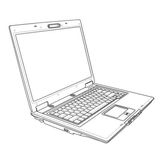
2. Knowing the Parts Basic sides of the Notebook PC NOTE: Photos and icons in this manual are used for artistic purposes only and do not show what is actually used in the product itself. Downloaded from LpManual.com Manuals... -
Page 12: Top Side
Knowing the Parts Top Side Refer to the diagram below to identify the components on this side of the Notebook PC. NOTE: The keyboard will be different for each territory. (Camera type depends on model) Multi-Position or Fixed Camera (depending on model) The built-in camera allows picture taking or video recording. -
Page 13: Display Panel
Knowing the Parts Keyboard LED Light (on selected models) The LED light mounted on the multi-position camera allows the user to light up the keyboard for typing in the dark or using the camera in the dark. Use [Fn B] to enable/disable the light. Camera Indicator The camera indicator shows when the built-in camera is in use. -
Page 14: Bottom Side
Knowing the Parts Bottom Side Refer to the diagram below to identify the components on this side of the Notebook PC. NOTE: The bottom side may vary in appearance depending on model. NOTE: The battery pack size will vary depending on model. -
Page 15: Battery Pack
Knowing the Parts Battery Lock - Spring The spring battery lock is used to keep the battery pack secured. When the battery pack is inserted, it will automatically lock. To remove the battery pack, this spring lock must be held in the unlocked position. Battery Pack The battery pack is automatically charged when the Notebook PC is connected to an AC power source and maintains power to the Notebook PC when AC power is not connected. -
Page 16: Right Side
Knowing the Parts Right Side Refer to the diagram below to identify the components on this side of the Notebook PC. ExpressCard Slot One 26pin Express card slot is available to support one ExpressCard/34mm or one ExpressCard/54mm expansion card. This new interface is faster by using a serial bus supporting USB 2.0 and PCI Express instead of the slower parallel bus used in the PC card slot. -
Page 17: Modem Port
Knowing the Parts TV-Out Port The TV-Out port is an S-Video connector that allows routing the Notebook PC’s display to a television or video projection device. You can choose between simultaneously or single display. Use an S-Video cable (not provided) for high quality displays or use the provided RCA to S-Video adapter for standard video devices. -
Page 18: Left Side
Knowing the Parts Left Side Refer to the diagram below to identify the components on this side of the Notebook PC. Kensington Lock Port ® The Kensington lock port allows the Notebook PC to be secured using Kensington com- ® ®... -
Page 19: Front Side
Knowing the Parts Front Side Refer to the diagram below to identify the components on this side of the Notebook PC. Wireless Switch Enables or disables the built-in wireless LAN and Bluetooth (selected models). When enabled, the wireless status indicator will light. Windows software settings are necessary before use. -
Page 20: Rear Side
Knowing the Parts Rear Side Refer to the diagram below to identify the components on this side of the Notebook PC. Power (DC) Input The supplied power adapter converts AC power to DC power for use with this jack. Power sup- plied through this jack supplies power to the Notebook PC and charges the internal battery pack. -
Page 21: Getting Started
3. Getting Started Using AC Power Using Battery Power Powering ON the Notebook PC Checking Battery Power Powering Options Power Management Modes Special Keyboard Functions Switches and Status Indicators NOTE: Photos and icons in this manual are used for artistic purposes only and do not show what is actually used in the product itself. -
Page 22: Power System
Getting Started Power System Using AC Power The Notebook PC power is comprised of two parts, the power adapter and the battery power system. The power adapter converts AC power from a wall outlet to the DC power required by the Notebook PC. -
Page 23: Using Battery Power
Getting Started Using Battery Power The Notebook PC is designed to work with a removable battery pack. The battery pack consists of a set of battery cells housed together. A fully charged pack will provide several hours of battery life, which can be further extended by using power management features through the BIOS setup. -
Page 24: Powering On The Notebook Pc
Getting Started Powering ON the Notebook PC The Notebook PC’s power-ON message appears on the screen when you turn it ON. If necessary, you may adjust the brightness by using the hot keys. If you need to run the BIOS Setup to set or modify the system configuration, press [F2] upon bootup to enter the BIOS Setup. -
Page 25: Checking Battery Power
Getting Started Checking Battery Power The battery system implements the Smart Battery standard under the Windows environment, which allows the battery to accurately report the amount of charge left in the battery. A fully-charged battery pack provides the Notebook PC a few hours of working power. But the actual figure varies depending on how you use the power saving features, your general work habits, the CPU, system memory size, and the size of the display panel. -
Page 26: Charging The Battery Pack
Getting Started Charging the Battery Pack Before you use your Notebook PC on the road, you will have to charge the battery pack. The battery pack begins to charge as soon as the Notebook PC is connected to external power using the power adapter. Fully charge the battery pack before using it for the first time. -
Page 27: Power Options
Getting Started Power Options The power switch turns ON and OFF the Notebook PC or putting the Notebook PC into sleep or hiberna- tion modes. Actual behavior of the power switch can be customized in Windows Control Panel “Power Options.” For other options, such as “Switch User, Restart, Sleep, or Shut Down,”... -
Page 28: Power Management Modes
Getting Started Power Management Modes The Notebook PC has a number of automatic or adjustable power saving features that you can use to maximize battery life and lower Total Cost of Ownership (TCO). You can control some of these features through the Power menu in the BIOS Setup. -
Page 29: Special Keyboard Functions
Getting Started Special Keyboard Functions Colored Hot Keys The following defines the colored hot keys on the Notebook PC’s keyboard. The colored commands can only be accessed by first pressing and holding the function key while pressing a key with a colored command. PUSH NOTE: The Hot Key locations on the function keys may vary depending on model but the functions should remain the same. -
Page 30: Colored Hot Keys (Cont)
Getting Started Colored Hot Keys (cont.) PUSH Speaker Icons (F10): Toggles the speakers ON and OFF (only in Windows OS) Speaker Down Icon (F11): Decreases the speaker volume (only in Windows OS) Speaker Up Icon (F12): Increases the speaker volume (only in Windows OS) Num Lk (Ins): Toggles the numeric keypad (number lock) ON and OFF. Allows you to use a larger portion of the keyboard for number entering. -
Page 31: Microsoft Windows Keys
Getting Started Microsoft Windows Keys There are two special Windows keys on the keyboard as described below. The key with the Windows Logo activates the Start menu located at the bottom left of the Win- dows desktop. The other key, that looks like a Windows menu with a small cursor, activates the properties menu and is equivalent to pressing the right mouse button on a Windows object. -
Page 32: Switches And Status Indicators
Getting Started Switches and Status Indicators Switches PUSH InstantFun PLUS Key Pressing this button will launch a multimedia player application to view DVDs, VCDs, videos, photos, or television programs (when equipped with a TV tuner); or listen to music CDs or files. Power4Gear eXtreme Key The Power4Gear eXtreme key toggles power savings between various power saving modes. -
Page 33: Status Indicators
Getting Started Status Indicators Front PUSH Battery Charge Indicator The battery charge indicator is an LED that shows the status of the battery’s power as follows: ON: The Notebook PC’s battery is charging when AC power is connected. OFF: The Notebook PC’s battery is charged or completely drained. Blinking: Battery power is less than 10% and the AC power is not connected. -
Page 34: Number Lock Indicator
Using the Notebook PC Status Indicators (cont.) PUSH Number Lock Indicator Indicates that number lock [Num Lk] is activated when lighted. Number lock allows some of the keyboard letters to act as numbers for easier numeric data input. Capital Lock Indicator Indicates that capital lock [Caps Lock] is activated when lighted. -
Page 35: Multimedia Control Keys (On Selected Models)
Using the Notebook PC Multimedia Control Keys (on selected models) The multimedia control keys allows for convenient controlling of the multimedia application. The fol- lowing defines the meaning of each multimedia control key on the Notebook PC. Use the [Fn] key in combination with the arrow keys for CD control functions. CD Play/Pause During CD stop, begins CD play. - Page 36 Using the Notebook PC Downloaded from LpManual.com Manuals...
-
Page 37: Using The Notebook Pc
4. Using the Notebook PC Pointing Device Storage Devices Expansion Card Optical drive Flash memory card reader Hard disk drive Memory (RAM) Connections Modem Connection Network Connection Wireless LAN Connection Bluetooth Wireless Connection Fingerprint Scanner (on selected models) Trusted Platform Module (TPM) (on selected models) NOTE: Photos and icons in this manual are used for artistic purposes only and do not show what is actually used in the product itself. -
Page 38: Pointing Device
Using the Notebook PC Pointing Device The Notebook PC’s integrated touchpad pointing device is fully compatible with all two/three-but- ton and scrolling knob PS/2 mice. The touchpad is pressure sensitive and contains no moving parts; Cursor therefore, mechanical failures can be avoided. A Movement device driver is still required for working with some Scroll Area... -
Page 39: Touchpad Usage Illustrations
Using the Notebook PC Touchpad Usage Illustrations Clicking/Tapping - With the cursor over an item, press the left button or use your fingertip to touch the touchpad lightly, keeping your finger on the touchpad until the item is selected. The selected item will change color. -
Page 40: Caring For The Touchpad
Using the Notebook PC Caring for the Touchpad The touchpad is pressure sensitive. If not properly cared for, it can be easily damaged. Take note of the following precautions. • Make sure the touchpad does not come into contact with dirt, liquids or grease. •... -
Page 41: Storage Devices
Using the Notebook PC Storage Devices Storage devices allow the Notebook PC to read or write documents, pictures, and other files to various data storage devices. This Notebook PC has the following storage devices: • Expansion Card • Optical drive •... -
Page 42: Optical Drive
Using the Notebook PC Optical Drive Inserting an optical disc 1. While the Notebook PC’s power is ON, press 2. Gently pull on the drive’s front panel and slide the drive’s eject button and the tray will eject the tray completely out. Be careful not to touch out partially. -
Page 43: Removing An Optical Disc
Using the Notebook PC Optical Drive (Cont.) Removing an optical disc Emergency eject Actual location will vary by model� Eject the tray and gently pry the edge of the disc The emergency eject is located in a hole on the op- tical drive and is used to eject the optical drive tray upwards at an angle to remove the disc from in case the electronic eject does not work. -
Page 44: Flash Memory Card Reader
Using the Notebook PC Flash Memory Card Reader Normally a memory card reader must be purchased separately in order to use memory cards from devices such as digital cameras, MP3 players, mobile phones, and PDAs. This Notebook PC has a single built-in memory card reader that can use many flash memory cards as shown in the example below. -
Page 45: Hard Disk Drive
Using the Notebook PC Hard Disk Drive Hard disk drives have higher capacities and operate at much faster speeds than floppy disk drives and optical drives. The Notebook PC comes with a replaceable hard disk drive. Current hard drives support S.M.A.R.T. (Self Monitoring and Reporting Technology) to detect hard disk errors or failures before they happen. -
Page 46: Memory (Ram)
Using the Notebook PC Memory (RAM) Additional memory will increase application performance by decreasing hard disk access. The BIOS automatically detects the amount of memory in the system and configures CMOS accordingly during the POST (Power-On-Self-Test) process. There is no hardware or software (including BIOS) setup required after the memory This is only an example�... -
Page 47: Connections
Using the Notebook PC Connections NOTE: The built-in modem and network cannot be installed later as an upgrade. After purchase, modem and/or network can be installed as an expansion card. Modem Connection The telephone wire used to connect the Notebook PC’s internal modem should have either two or four wires (only two wires (telephone line #1) is used by the modem) and should have an RJ-11 connector on both ends. -
Page 48: Network Connection
Using the Notebook PC Network Connection Connect a network cable, with RJ-45 connectors on each end, to the modem/network port on the Note- book PC and the other end to a hub or switch. For 100 BASE-TX / 1000 BASE-T speeds, your network cable must be category 5 or better (not category 3) with twisted-pair wiring. -
Page 49: Infrastructure Mode
Using the Notebook PC Wireless LAN Connection (on selected models) The optional built-in wireless LAN is a compact easy-to-use wireless Ethernet adapter. Implementing the IEEE 802.11 standard for wireless LAN (WLAN), the optional built-in wireless LAN is capable of fast data transmission rates using Direct Sequence Spread Spectrum (DSSS) and Orthogonal Frequency Division Multiplexing (OFDM) technologies on 2.4GHz/5GHz frequencies. -
Page 50: Windows Wireless Network Connection
Using the Notebook PC Windows Wireless Network Connection Connecting to a network 1� Switch ON the Wireless Switch if necessary for your model (see switches in Section 3)� 2� Press [FN F2] repeatedly until Wireless LAN 2b� Or double click the Wireless Console icon on ON or WLAN &... -
Page 51: Bluetooth Wireless Connection (On Selected Models)
Using the Notebook PC Bluetooth Wireless Connection (on selected models) Notebook PCs with Bluetooth technology eliminates the need for cables for connecting Bluetooth-enabled devices. Examples of Bluetooth-enabled devices may be Notebook PCs, Desktop PCs, mobile phones, and PDAs. Note: If your Notebook PC did not come with built-in Bluetooth, you need to connect a USB or ExpressCard Bluetooth module in order to use Bluetooth. -
Page 52: Clearing Tpm Secured Data
Using the Notebook PC Trusted Platform Module (TPM) (on selected models) The TPM, or Trusted Platform Module, is a security hardware device on the system board that will hold computer-generated keys for encryption. It is a hardware-based solution that an help avoid attacks by hackers looking to capture passwords and encryption keys to sensitive data. -
Page 53: Fingerprint Registration (On Selected Models)
Using the Notebook PC Fingerprint Registration (on selected models) The fingerprint scanner can be used for instant and secure user authentication. These instructions will show you how to setup the fingerprint registration. PUSH 2� Select “Fingerprints” and click Next. 1� This wizard will automatically start when TPM is enabled in BIOS (see Appendix)�... - Page 54 Using the Notebook PC Fingerprint Registration (on selected models) cont. 6� Click Finish when done� 5. Select a finger on the diagram and swipe the corresponding finger on the scanner slowly. You must swipe your finger multiple times for verification. You must register at least two fingers to decrease the chance of any problems�...
-
Page 55: 3G Watcher Software
Using the Notebook PC 3G Watcher Software The 3G Watcher software application will allow your Notebook PC to connect to 3G wire- less networks normally used by 3G mobile phones. When connected, your Notebook PC can connect to the Internet just like using a wireless network. A shortcut to the 3G Watcher application will be placed on your desktop. - Page 56 Using the Notebook PC Watcher window Icons and indicators on the main window The main Watcher window provides status information and allows you to initiate and monitor data con- nections or make and receive phone calls (if voice is supported by your 3G modem and your service provider).
- Page 57 Using the Notebook PC Roaming. You are connected to a network other than your local service provider’s. There may be a surcharge for roaming service. (This service may not be available.) New SMS message. Click the icon to open the SMS Express window and read your messages. When your SIM becomes full, this icon flashes and turns red.
- Page 58 Using the Notebook PC Downloaded from LpManual.com Manuals...
-
Page 59: Appendix
Appendix Optional Accessories & Connections Operating System and Software System BIOS Settings Common Problems and Solutions Windows Software Recovery Glossary Declarations and Safety Statements Notebook PC Information NOTE: Photos and icons in this manual are used for artistic purposes only and do not show what is actually used in the product itself. -
Page 60: Optional Accessories
Appendix Optional Accessories These items, if desired, come as optional items to complement your Notebook PC. USB Hub (Optional) Attaching an optional USB hub will increase your USB ports and allow you to quickly connect or disconnect many USB peripherals through a single cable. USB Flash Memory Disk A USB flash memory disk is an optional item that can replace the 1.44MB floppy disk and provide storage up to several hundred megabytes, higher transfer speeds,... -
Page 61: Optional Connections
Appendix Optional Connections These items, if desired, may be purchased from third-parties. USB Keyboard and Mouse Attaching an external USB keyboard will allow data entry to be more comfortable. Attaching an external USB mouse will allow Windows navigation to be more comfortable. Both the external USB keyboard and mouse will work simultaneously with the Notebook PC’s built-in keyboard and touchpad. - Page 62 Appendix Bluetooth Mouse Setup (optional) This process can be used to add most Bluetooth devices in Windows operating system. 1� Switch ON the Wireless Switch if necessary for your model (see switches in Section 3)� 2b� Or double click the Wireless Console icon on 2�...
- Page 63 Appendix 5� Click Next when the Bluetooth mouse 6� A list of nearby Bluetooth devices will is ready� be shown� Select the Bluetooth mouse and click Next� 8� Wait while the Bluetooth mouse is being 7� Select “Don’t use a passkey” and click added�...
-
Page 64: Operating System And Software
Appendix Operating System and Software This Notebook PC may offer (depending on territory) its customers the choice of a pre-installed Micro- soft Windows operating system. The choices and languages will depend on the territory. The levels of hardware and software support may vary depending on the installed operating system. The stability and compatibility of other operating systems cannot be guaranteed. -
Page 65: System Bios Settings
Appendix System BIOS Settings Boot Device 1. On the Boot screen, select Boot Device Priority. 2. Select each item and press [Enter] to select a device. Security Setting To clear the password: 2. Type in a password and press [Enter]. 1. -
Page 66: Save Changes
Appendix System BIOS Settings (cont.) Password Check User Access Level Select whether to ask for a password during bootup (Always) Select the level of access to allow the “User Password” to or only when entering the BIOS setup utility (Setup). have in the BIOS setup utility. -
Page 67: Common Problems And Solutions
A. Reinstall the “ATK0100” driver from the driver CD or download it from the ASUS website. Hardware Problem - Built-in Camera The built-in camera does not work correctly. 1. Check “Device Manager” to see if there are any problems. 2. Try reinstalling the webcam driver to solve the problem. 3. If the problem is not solved, update the BIOS to the latest version and try again. 4. If the problem still exist, contact your local service center and ask an engineer for assistance. Hardware Problem - Battery Battery maintenance. 1. Register the Notebook PC for a one-year-warranty using the following website: http://member.asus.com/login.aspx?SLanguage=en-us 2. Do NOT remove the battery pack while using the Notebook PC with the AC adaptor to prevent damage caused by the accidental power loss. The ASUS battery pack has protection circuitry to prevent over-charging so it will not damage the battery pack if it is left in the Notebook PC. 3. Store the battery pack in a dry location with temperatures between 10℃ and 30℃ if you will not be using it for a long time. It is strongly recommended that you charge the battery pack every three months. Downloaded from LpManual.com Manuals... - Page 68 Diagnostics: 1. Power On by Battery only? (Y = 2, N = 4) 2. Able to see BIOS (ASUS Logo)? (Y = 3, N = A) 3. Able to load the OS? (Y = B, N = A) 4. Adapter power LED ON? (Y = 5, N = C) 5.
- Page 69 4. Update the BIOS to the latest version with WINFLASH in Windows or AFLASH in DOS mode. These utilities and BIOS files can be downloaded from the ASUS website. (WARNING: Make sure your Notebook PC does not loose power during the BIOS flashing process.) 5.
- Page 70 Reboot the system. Assuming that you have successfully flashed the BIOS file, press [F2] to enter BIOS setup page when the ASUS logo appears during system boot-up. f. After entering BIOS setup page, go to Exit page and choose Load Manufacture Defaults.
- Page 71 Appendix Common Problems and Solutions (Cont.) Symantec’s Norton Internet Security (NIS) 1. Sometimes NIS will show an alert to stop a Trojan virus from a local IP address. This problem can be solved by making sure the virus definition file is the latest one and regularly updating the virus definition file. 2. Reinstalling fails at the “Information Wizard” after uninstalling Norton Antivirus. Make sure NIS has been uninstalled from your computer, reboot your system, install NIS again, use “Live Update”...
- Page 72 Appendix Common Problems and Solutions (Cont.) 9. Windows Firewall must be stopped before installing “Norton Internet Security” or “Norton Personal Firewall”. How to stop Windows Firewall: 1. Click Start and then Control Panel. 2. You will have one of two control panels. Click on the Security Center icon. 3. Click on the Windows Firewall icon beneath the status updates. 4. Click Off and then click OK. 10. Why is the “Privacy Control” icon showing ‘x’? Turn off Privacy Control from “Status &...
-
Page 73: Windows Vista Software Recovery
1. Press [F9] during bootup (requires a Recovery Partition) 2. Press [Enter] to select Windows Setup [EMS Enabled] 3. Read the “ASUS Preload Wizard” screen and click Next. 4. Select a partition option and click Next. Partition options: Recover Windows to first partition only. - Page 74 4. Follow the on-screen instructions to complete the recovery process. WARNING: Do not remove the Recovery CD (unless instructed to do so) during the recovery process or else your partitions will be unusable. NOTE: Please visit www.asus.com for updated drivers and utilities. Downloaded from LpManual.com Manuals...
-
Page 75: Glossary
Appendix Glossary ACPI (Advanced Configuration and Power Management Interface) Modern standard for reducing power usage in computers. APM (Advanced Power Management) Modern standard for reducing power usage in computers. AWG (American Wire Gauge) NOTE: This table is for general reference only and should not be used as a source of the American Wire Gauge standard as this table may not be current or complete. - Page 76 Appendix Glossary (Cont.) CPU (Central Processing Unit) The CPU, sometimes called “Processor,” actually functions as the “brain” of the computer. It interprets and executes program commands and processes data stored in memory. Device Driver A device driver is a special set of instructions that allows the computer’s operating system to communicate with devices such as VGA, audio, Ethernet, printer, or modem.
- Page 77 Appendix Glossary (Cont.) Kensington Locks ® Kensington locks (or compatible) allow the Notebook PC to be secured usually using a metal cable and ® lock that prevent the Notebook PC to be removed from a fixed object. Some security products may also include a motion detector to sound an alarm when moved.
-
Page 78: Suspend Mode
Appendix Glossary (Cont.) RAM (Random Access Memory) RAM (usually just called memory) is the place in a computer where the operating system, applica- tion programs, and data in current use are temporarily kept so that they can be quickly reached by the computer’s processor instead of having to read from and write to slower storage such as the hard disk or optical disc. -
Page 79: Declarations And Safety Statements
Appendix Declarations and Safety Statements DVD-ROM Drive Information The Notebook PC comes with an optional DVD-ROM drive or a CD-ROM drive. In order to view DVD titles, you must install your own DVD viewer software. Optional DVD viewer software may be purchased with this Notebook PC. -
Page 80: Internal Modem Compliancy
Appendix Internal Modem Compliancy The Notebook PC with internal modem model complies with JATE (Japan), FCC (US, Canada, Korea, Taiwan), and CTR21. The internal modem has been approved in accordance with Council Decision 98/482/EC for pan-European single terminal connection to the public switched telephone network (PSTN). - Page 81 Appendix Internal Modem Compliancy (Cont.) This table shows the countries currently under the CTR21 standard. Country Applied More Testing Austria Belgium Czech Republic Not Applicable Denmark Finland France Germany Greece Hungary Not Applicable Iceland Ireland Italy Still Pending Still Pending Israel Lichtenstein Luxemburg The Netherlands...
-
Page 82: Federal Communications Commission Statement
Appendix Federal Communications Commission Statement This device complies with FCC Rules Part 15. Operation is subject to the following two conditions: • This device may not cause harmful interference, and • This device must accept any interference received, including interference that may cause undesired operation. -
Page 83: Fcc Radio Frequency Interference Requirements
Appendix FCC Radio Frequency Interference Requirements This device is restricted to INDOOR USE due to its operation in the 5.15 to 5.25GHz frequency range. FCC requires this product to be used indoors for the frequency range 5.15 to 5.25GHz to reduce the potential for harmful interference to co-channel of the Mobile Satellite Systems. -
Page 84: Wireless Operation Channel For Different Domains
Appendix Wireless Operation Channel for Different Domains N. America 2.412-2.462 GHz Ch01 through CH11 Japan 2.412-2.484 GHz Ch01 through Ch14 Europe ETSI 2.412-2.472 GHz Ch01 through Ch13 France Restricted Wireless Frequency Bands Some areas of France have a restricted frequency band. The worst case maximum authorized power indoors are: •... -
Page 85: Ul Safety Notices
Appendix UL Safety Notices Required for UL 1459 covering telecommunications (telephone) equipment intended to be electrically connected to a telecommunication network that has an operating voltage to ground that does not exceed 200V peak, 300V peak-to-peak, and 105V rms, and installed or used in accordance with the National Electrical Code (NFPA 70). - Page 86 Appendix Nordic Lithium Cautions (for lithium-ion batteries) CAUTION! Danger of explosion if battery is incorrectly replaced. Replace only with the same or equivalent type recommended by the manufacturer. Dispose of used bat- teries according to the manufacturer’s instructions. (English) ATTENZIONE! Rischio di esplosione della batteria se sostituita in modo errato. Sosti- tuire la batteria con un una di tipo uguale o equivalente consigliata dalla fabbrica.
-
Page 87: Optical Drive Safety Information
Appendix Optical Drive Safety Information Laser Safety Information Internal or external optical drives sold with this Notebook PC contains a CLASS 1 LASER PRODUCT. Laser classifications can be found in the glossary at the end of this user’s manual. WARNING: Making adjustments or performing procedures other than those specified in the user’s manual may result in hazardous laser exposure. - Page 88 Appendix CTR 21 Approval (for Notebook PC with built-in Modem) Danish Dutch English Finnish French German Greek Italian Portuguese Spanish Swedish Downloaded from LpManual.com Manuals...
- Page 89 Appendix Downloaded from LpManual.com Manuals...
-
Page 90: Notebook Pc Information
Appendix Notebook PC Information This page is provided for recording information concerning your Notebook PC for future reference or for technical support. Keep this User’s Manual in a secured location if passwords are filled out. Owner’s Name: ___________________________ Owner’s Telephone: ______________ Manufacturer: _______________ Model: ___________ Serial Number: ______________ Display Size: ___________ Resolution: _____________Memory Size: ______________ Retailer: _________________Location: ___________ Purchase Date: ______________... -
Page 91: Copyright Information
ASUS will only be responsible for or indemnify you for loss, damages or claims based in contract, tort or infringement under this Warranty Statement. This limit also applies to ASUS’ suppliers and its reseller. It is the maximum for which ASUS, its sup- pliers, and your reseller are collectively responsible.
Need help?
Do you have a question about the E3108 and is the answer not in the manual?
Questions and answers