Table of Contents
Advertisement
Advertisement
Table of Contents

Subscribe to Our Youtube Channel
Related Manuals for mcmurdo R5 GMDSS VHF


Summary of Contents for mcmurdo R5 GMDSS VHF
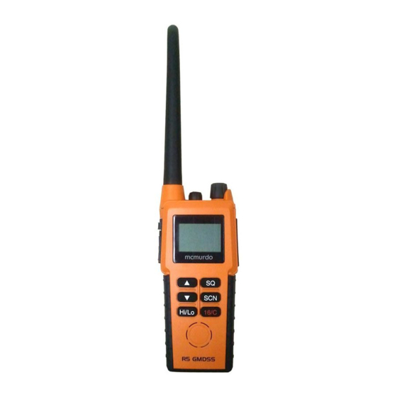
- Page 1 R5 GMDSS VHF Handheld Radio USER MANUAL...
- Page 2 Emergency procedure • R emove the top-seal of the yellow emergency battery package. • I nsert the battery package into the handheld transceiver. • T urn the knob at the top of the radio clockwise. The display lights u p showing the last used channel and the battery level. • S elect channel 16 (Distress or Safety), press the 16/C key. • P ress the PTT and say: — “MAYDAY, MAYDAY, MAYDAY”, — “This is”..ships name repeated three times — — “MAYDAY” — “This is”..ships name and call sign, — The ship’s position in latitude and longitude or other reference to a known geographical location, — The nature of distress and assistance wanted, — Any other information which might facilitate the rescue. — “OVER”...
- Page 3 Orolia Ltd. No liability can be accepted for any inaccuracies or omissions in the publication, although every care has been taken to make it as complete and accurate as possible. This manual is applicable for McMurdo R5 GMDSS VHF handheld radios manufactured after October 2012.
-
Page 4: Warranty Statement
All enquiries relating to this warranty or Approved Service Agents should be sent to: Orolia Ltd, Silver Point, Airport Service Road, Portsmouth, Hampshire, PO3 5PB, UK Telephone: Int + 44 (0) 23 9262 3900 Fax: Int + 44 (0) 23 9262 3998 Web: www.mcmurdomarine.com Email: service.mcmurdo@orolia.com An Orolia Group Business 1211... - Page 5 END OF LIFE STATEMENT Disposal The Waste Electrical and Electronic Equipment (WEEE) Directive aims to minimise any adverse impact of electronic equipment on the environment, both during the product lifetime and when it becomes waste. Within the European Union this legislation is mandated by Directive 2002/96/EC, and there is similar legislation in most other continents.
- Page 6 Precautions Avoid water and salt in the I/O connector and keep it clean frequently. Only use original battery packs. Make sure they are clean and dry before attaching the transceiver. Be careful not to damage any gaskets. Only use the original charger for the rechargeable battery.
- Page 7 Training information McMurdo R5 GMDSS VHF is designed for "occupational use only". It must be operated by licensed personnel only. The R5 complies with the FCC RF exposure limits for "Occupational Use Only". • FCC OET Bulletin 65 Supplement C, evaluating compliance with FCC guidelines for human exposure to radio frequency electromagnetic fields.
-
Page 9: Table Of Contents
Contents Chapter 1 Introduction Your GMDSS VHF ..............1 Performance ...............2 Channels ................2 Chapter 2 Operation Controls ................3 Keys and buttons ..............3 The display .................5 Using the GMDSS VHF ............6 Basic functions ..............6 Other functions ..............9 Configuring the GMDSS VHF ..........11 Entering and using configuration mode ...... - Page 10 Attaching and removing the belt clip ........ 23 Attaching the lanyard ............23 Chapter 5 Troubleshooting Displaying errors .............. 25 App. A Technical specifications Technical data R5 GMDSS VHF .......... 27 General ................27 Transmitter ...............28 Receiver ................28 Battery life guidelines ............29 Dimensional drawing, transceiver ........30 Dimensional drawing, chargers .........31...
-
Page 11: Chapter 1 Introduction
Chapter 1 Introduction Your GMDSS VHF Your portable VHF transceiver, is approved to fulfil the GMDSS requirements for portable VHF radios for Safety at Sea and is waterproof to the IP67 standard. As part of the required safety equipment, the R5 is to be used in an emergency situation. -
Page 12: Performance
Introduction Performance For best performance of the transceiver keep the following in mind: • Keep clear of metal environment. • Hold the transceiver vertically and 10 cm from lips and push the PTT when transmitting. • In receive mode carry the transceiver vertically with belt clips. •... -
Page 13: Controls
Chapter 2 Operation Controls Keys and buttons 1. On/off/volume 2. Light/Lock 3. Push To Talk (PTT) 4. Up key 5. Down key 6. Hi/Lo output power 7. Squelch 8. Scan 9. Priority channel (16)/ Call channel 10. Loudspeaker/microphone... - Page 14 Operation Key presses Pressing and holding certain keys gives access to additional functions, shown in the table below. Extra long Short press Long press press (1 beep) (2 beeps) (3 beeps) Show next available Run through available Run through item in the list (up or items, or available down).
-
Page 15: The Display
Operation The display The display holds various fields of information, explained below. 1. Current working channel. 2. Current channel mode. 3. “Lo”: Reduced transmitter power. Full transmitter power is not shown in display. 4. Dual watch activated. 5. Current working channel is marked for scanning. 6. -
Page 16: Using The Gmdss Vhf
Operation Using the GMDSS VHF Basic functions Note Before using the radio, mount the antenna at the top of the radio. The antenna is delivered with the radio. Switching the radio on and off • To switch the radio on, turn the knob at the top of the radio clockwise. -
Page 17: Adjusting The Volume
Operation Activating a call To activate a call to the selected channel, press and hold the PTT button on the side of the radio. The radio transmits as long as the PTT button is pressed. A small Tx sign next to the channel num- ber indicates when the radio is in transmit mode. - Page 18 Operation Using Dual watch To activate Dual watch, press the SCN key. The display shows “Dual” at the top and “16” at the bottom right. The radio toggles between the selected channel and channel 16. • To terminate Dual watch, press SCN again. Scanning channels •...
-
Page 19: Other Functions
Operation Other functions Programming the Call channel To program the Call channel, do as follows: 1. Press and hold 16/C until the current Call channel number is flashing. 2. Select the channel with or . 3. Press 16/C to confirm. Programming the scanning memory To add a channel to the scanning memory, select the channel and then press and hold the SCN key until the display shows MEM at the top. - Page 20 Operation “ALIVE” function is also deactivated when • The channel is changed. • The radio is turned OFF and ON again. • Watch or scanning is enabled. • Squelch is open. Refer to ALIVE on page 13 12110643...
-
Page 21: Configuring The Gmdss Vhf
Operation Configuring the GMDSS VHF Entering and using configuration mode Note The radio is not operational in configuration mode. • To enter configuration mode, press and hold the Light/Lock button while turning on the radio. The bottom line of the display shows the current menu item/setting. •... -
Page 22: Configuration Settings
Operation Configuration settings Configuration mode is used to program preferred channels and volume of key beep and battery alarm. The following settings are available in configuration mode. BEEP Status click/beep sound on key press, long press (settings/programming saved) and battery alarm. Maximum level. Status click/beep sound on key press, long press (settings/programming saved) and battery alarm. - Page 23 Operation ALIVE Factory default state. Press to set “ALIVE” on. ADD NAME A-Z, 0-9 Makes it possible to name the channels. The name must contain a maximum of 9 characters, use only capital letters, digits and spaces. Press Light/Lock to confirm programming. Note: The name appears in the service line on the display.
- Page 24 Operation 1211...
-
Page 25: Chapter 3 Batteries
Chapter 3 Batteries Battery types • The yellow primary battery pack contains a non-rechargeable Lithium battery. This battery pack is only to be used in case of emergency. • The black secondary battery pack contains a rechargeable battery. This battery pack is for daily use. The primary battery The yellow primary battery pack is only for emergency use, Important... -
Page 26: The Secondary Battery
Batteries The secondary battery Battery level indication The black secondary battery pack is for daily use of the radio. When the battery level is low, you should recharge the battery. The radio display shows the battery status. When the battery symbol is empty and flashing, the battery should be recharged as soon as possible. -
Page 27: The Battery Charger
Batteries The battery charger The chargers has two compartments. Single Charger Kit • A rear compartment only for storing a spare battery. It does not have a charger function. • A front compartment for recharging the battery alone or while attached to the radio. Single Charger Accessory Option Secondary battery (black, rechargeable) Single Charger Base... -
Page 28: Installing The Charger
Batteries Installing the charger Mounting the charger There are several options for mounting one or more chargers on a table or a wall. For information on dimensions and screw positions, refer to Dimensional drawing, chargers on page 31. When mounting the charger, make sure it is placed in a dry place and away from direct sunlight. - Page 29 Batteries • Quick red flash (twice per second): Charging error, e.g. battery defect or temperature out of range. • Steady red light: Charging completed. Trickle charge mode. Charging time with emtpy battery: VHF off approx. 4 hours, VHF on: approx. 5 hours. The battery indicator on the radio display indicates if the radio is placed in the charger while radio and charger are both...
- Page 30 Batteries...
-
Page 31: Chapter 4 Equipment And Accessories
Chapter 4 Equipment and accessories External equipment The R5 VHF radio accessory connector can support remote handset or headset connection. Contact the suppler of the accessory device for detailed connection information. When external equipment is connected to the radio, the right side of the display will show a headset. -
Page 32: Accessories
Equipment and accessories Accessories List of accessories The following accessories are delivered with your radio: Accessory Primary battery non rechargeable, B3502 Belt clip Antenna Lanyard User Manual (this manual) Batteries, charger, AC/DC Converter and 12VDC Connection are described inBatteries on page 15. To mount the antenna, simply screw it into the threaded bush at the top of the radio. -
Page 33: Attaching And Removing The Belt Clip
Equipment and accessories Attaching and removing the belt clip To attach the belt clip, slide the belt clip upwards into the rails at the back of the radio until it locks. To remove the belt clip, press the projection at the top of the belt clip to release the lock and slide the belt clip downwards out of the rails. - Page 34 Equipment and accessories 0740...
-
Page 35: Chapter 5 Troubleshooting
Chapter 5 Troubleshooting Displaying errors Some errors result in an error message in the display. These error messages are listed below. Display text Problem Type Actions The battery voltage is Severe. Change/recharge below a critical level, Radio is non- the battery. EMPTY BAT where further operation functional. - Page 36 Troubleshooting 0845...
-
Page 37: Technical Specifications
Appendix A Technical specifications Technical data R5 GMDSS VHF General Item Specification RX frequency range 155.000 - 163.425 MHz TX frequency range 155.000 - 161.450 MHz Modulation 16K0G3E Power supply 7.2 VDC Li battery Current drain at 2 W TX 1.4 A... -
Page 38: Transmitter
Technical specifications Transmitter Item Specification RF output power W /1 W RF output power, Canada 2.5 W ±1 dB / 0.75 W ±1 dB Max deviation ±5 kHz Spurious emission < 0.25 uW Adjacent channel power > 70 dB Receiver Item Specification Sensitivity (20 dB SINAD) -
Page 39: Battery Life Guidelines
Technical specifications Battery life guidelines New batteries should be placed in the charger for minimum 12 Note hours first time. During daily use, always keep the battery fully charged and away from hot areas. Keep the battery terminals dry and clean. Never discharge beyond the specifications of the battery. -
Page 40: Dimensional Drawing, Transceiver
Technical specifications Dimensional drawing, transceiver 0709... -
Page 41: Dimensional Drawing, Chargers
Technical specifications Dimensional drawing, chargers Mounting Possibillities Desktop mounting, top view Wall mounting, rear view 0740... - Page 42 Technical specifications 0703...
-
Page 43: Attention
Appendix B Attention Gore-Tex Membrane To keep the VHF watertight, is it very important that the Gore-Tex membrane under no circumstances must be damaged/covered or removed. That is, do not remove the Gore-Tex membrane or place any labels in the area. - Page 44 Attention 0740...
- Page 46 Orolia Ltd Silver Point Airport Service Road Portsmouth PO3 5PB United Kingdom Phone: +44 (0)23 9262 3900 Fax: +44 (0)23 9262 3998 Email: service.mcmurdo@orolia.com Website: www.mcmurdomarine.com 20-150 Issue 3 An Orolia Group Business...
Need help?
Do you have a question about the R5 GMDSS VHF and is the answer not in the manual?
Questions and answers