
Related Manuals for King Kutter Rotary Mower


Summary of Contents for King Kutter Rotary Mower
-
Page 1: Rotary Mower
PO Box 1200 305 Commerce Drive Winfield, Alabama 35594 ROTARY MOWER OPERATION AND PARTS MANUAL Part No 999998 www.kingkutter.com... -
Page 3: Customer Information
TO THE PURCHASER This manual contains valuable information about your new King Kutter Mower. It has been carefully prepared to give you helpful suggestions for operating, adjusting, servicing and ordering repair parts. Keep this manual in a convenient place for quick and easy reference. - Page 4 Kutter dealer, from where it was purchased, for service or replacement of defective parts that are covered by warranty. (The King Kutter Factory may inspect equip- ment or parts before warranty claims are honored.) Payment of all costs incurred by the dealer for traveling to or transporting the equipment for warranty inspec- tion and or claims.
-
Page 5: Table Of Contents
CONTENTS ITEM PAGE Safety ... 6 Assembly Instructions ... 8 Before Putting Into Service ... 11 Safety Training ... 12 Operational Safety ... 14 Transportation Safety ... 16 Attaching To Tractor ... 17 Sizing PTO ... 19 Operating Instructions... 20 Maintenance ... -
Page 6: Signal Words
It may also be used to alert against unsafe practices. If you have any questions not answered in this manual or require additional copies or the manual is damaged, please contact your dealer or King Kutter, Inc. P.O. Box 1200 Winfield, AL 35594 (205) 487-3202 or www.kingkutter.com... -
Page 7: Equipment Safety Guidelines
Refer also to safety mes- sages and operation instruction in each of the appropriate sections of the tractor and mower manuals. Pay close attention to the safety signs affixed to the tractor and the rotary mower. -
Page 8: Assembly Instructions
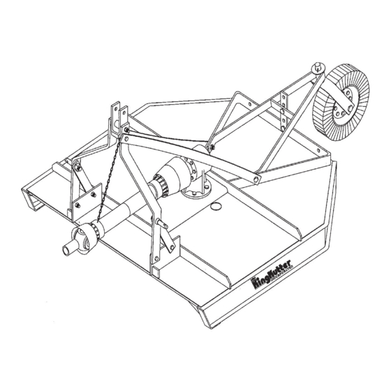
ROTARY MOWER ASSEMBLY INSTRUCTIONS STEP 1 Place rotary mower on a flat, level surface. STEP 2 Remove the wired on PTO shaft, lift pins, and spacers. Loosen and re- move the(4) bolts on the lift arm brackets, that secure the lift arm support straps, lift arms, and lift arm braces from the shipping positions and set aside. - Page 9 STEP 7 Using the right side lift arm as a lever, pull to the outside of the lift arm bracket and inset bolt through lift arm and lift arm bracket. (See Figure I) In- stall washer and nut. Place the lift pin in the larger of the (2) holes on the lift arm brace and loosley attach the lift arm.
- Page 10 Figure E Figure F Figure G Figure H Figure I...
-
Page 11: Before Putting Into Service
For all Grease Fittings use TYPE/grade II tube grease. • STEP 1 Place rotary mower so that the deck is secure and level. STEP 2 Remove 1/2” Pipe Plug (Located at top of gearbox) and 1/8” Pipe Plug (located at lower 1/3 of gearbox. -
Page 12: Safety Training
If this machine is used by any person other than you, or is loaned or rented, it is the rotary mower owner’s respon- sibility to make certain that owner's manual be available to the operator prior to operating: 1- Reads and understands the operator’s manuals. - Page 13 PREPARTION Never operate the tractor and mower until you have read and completely understand this manual, the Tractor Operator’s Manual, and each of the safety messages found on the safety signs on the tractor and mower. Personal protection equipment including hardhat, safety glasses, safety shoes, and gloves are recommended during assembly, installation, operation, adjustment, mainte- nance, repairing, removal, or moving the implement.
-
Page 14: Operational Safety
The rotary mower is designed for use only on tractors with 540-RPM power take off. Install and secure all guards and shields before starting or operating. The flaps, driveline guards and tractor shields should be used and maintained in good working condition. - Page 15 Do not reach or place any part of your body under equipment until it is blocked securely. Do not allow riders on the rotary mower or tractor at anytime. There is no safe place for any riders. Do not operate unless all personnel, livestock, and pets are several hun- dred feet away to prevent injury by thrown objects.
-
Page 16: Transportation Safety
OPERATIONAL SAFETY continued... Pass rotary mower diagonally through sharp dips and avoid sharp drops to prevent “hanging up” tractor and rotary mower. Practice will improve your skills in maneuvering on rough terrain. Always cut down slopes, never across the face. Always check tractor manual for proper use on slopes. -
Page 17: Attaching To Tractor
PTO shafts to be shortened as described by the following steps. STEP 3 Raise and lower rotary mower in order to locate the shortest distance be- tween equipment gearbox input shaft and tractor PTO output shaft. With the rotary mower in the shortest distance position shut down the tractor and SE- CURELY BLOCK ROTARY MOWER IN POSITION. - Page 18 Raise rotary mower and remove blocking. Raise and lower rotary mower in order to locate the longest distance between equipment input shaft and the tractor PTO output shaft. With the rotary mower in the longest distance position, shut down the tractor and SECURELY BLOCK THE ROTARY MOWER IN POSITION.
-
Page 19: Sizing Pto
SIZING PTO SHAFT STEP 1 Cutting the PTO shaft to length. NOTE: Be sure to cut equal lengths of each PTO shaft section. Clamp end of PTO shaft in a vice and cut off shield where marked. 1-A & 1-B) STEP 2 Using cut section of the shield as a guide cut shaft off the same amount. -
Page 20: Operating Instructions
OPERATING INSTRUCTIONS This mower was designed to CUT PASTURE GRASS AND ROUGH AREAS UP TO 1" IN DIAMETER.. Use of your rotary mower to cut any material larger than 1" in diameter may damage the mower and void your warranty. - Page 21 540 PTO RPM and thus maximum blade tip speed. NOTE: Do not allow the tractor engine or rotary mower to bog down or stall. This causes undue wear and tear on the mower and tractor. If this continues to happen reduce ground speed and raise cutting height of rotary mower until the 540 PTO RPM is able to be maintained.
-
Page 22: Maintenance
MAINTENANCE 1). Periodically check and maintain proper gear oil level. 2). Every 8 hours, wheel fork(s), wheel hub(s), PTO shaft universal joints (2), and PTO telescoping surface. (See Figures M-1 & M-2) NOTE: Use only a grade Type II tube grease. 3). -
Page 23: Maintenance Safety
MAINTENANCE SAFETY Good maintenance is your responsibility. Poor maintenance is an invitation to trouble. Follow good shop practices. Keep service area clean and dry Be sure electrical outlets and tools are properly grounded Use adequate light for the job at hand. Make sure there is plenty ventilation. -
Page 24: Safety Sign Locations
SAFETY SIGN LOCATIONS The types of safety signs and locations on the equipment are shown in the illustra- tion below. Good safety requires that you familiarize yourself with the various safety signs, the type of warning and the area, or particular function related to that area, that requires your SAFETY AWARENESS REMEMBER: If safety signs have been damaged, removed, become illegible or parts have been replaced without signs, new safety signs must be applied. -
Page 29: Pto Shaft Parts
Ref. Part Name Roll Pin Kit Male Tube End Yoke Implement End Yoke Female Tube End Yoke Tractor End Yoke Inner Tube Outter Tube Cross Kit #4 Quick Disconnect Pin Safety Shield BYPY Safety Shield Eurocardan **Must specify name brand of PTO. Part Number 147022 147029... - Page 30 SLIP CLUTCH PTO SHAFT Ref. Part Name Cross Kit Roll Pin Female Tube End Yoke Inner Tube Slip Clutch Assembly Male Tube End Yoke Outer Tube Tractor End Yoke Quick Disconnect Pin Safety Shield BYPY Safety Shield Eurocardan Part Number 147129 170015 170120...
-
Page 31: Slip Clutch Assembly
SLIP CLUTCH ASSEMBLY Ref. Clutch Spring with Compression Bolts & Nuts (Pkg 8) Slip Clutch Lock Bolt Slip Clutch Liner Plate Pressure Plate Part Name Flanged Yoke Sleeve Clutch Plate Friction Hub Part Number 7" 8" 500140 500140 196006 196011 196005 196005 196008... -
Page 32: Replacement Parts
Swivel Kit Wheel Washer Kit Shear Bolt Kit (Pkg. 5) * Depending on the size of rotary mower purchased, the blade carrier can be any of these 2 types. ** 40" Mower doesn't have a swivel. Part Number 40"- 40hp 4'- 40hp 5'- 40hp 5'- 60hp... - Page 33 CAT. 2 Lift Pins (Pkg. of 2) Swivel Yoke Assembly Blade Bolt Set (Pkg. of 2) Mower Blade Set(Pkg. of 2) Part Name Rotary Mower Size Tire & Rim /w Hub Wheel Hub Assembly A-Frame Assembly A-Frame Ht. Adj. Gear Box...
- Page 34 HEAVY DUTY LIFT 6' & 7' MOWER Ref. Rotary Mower Size Tire & Rim /w Hub Wheel Fork Assembly Wheel Hub Assembly Cross Axle Assembly Lift Arm Brace PTO Shaft Lift Arm Assembly Swivel Yoke Assembly CAT. 2 Lift Pins (Pkg. of 2)
- Page 35 ROTARY MOWER - PULL Ref. Part Name Rotary Mower Size Tire & Rim /w Hub Cross Axle Assembly Wheel Hub Assembly Top Link CAT. 1 Gear Box PTO Shaft Pull Tongue Assembly Axle Cuff Stump Jumper Blade Bolt Set (Pkg. of 2) Mower Blade Set(Pkg.
- Page 36 Ref. Rotary Mower Size Cross Axle Assembly Wheel Hub Assembly Pull Arm (Fits Left or Right Side) Swivel Yoke Assembly Blade Bolt Set (Pkg. of 2) Mower Blade Set (Pkg. of 2) 7' PULL MOWER Part Name Tire & Rim /w Hub...
-
Page 37: Pto Shaft Cover Removal
PTO SHAFTS COVER REMOVAL BONDIOLI- (BYPY) There are 3 white tabs around the cover as shown in (A in FIG. 1). Take a screwdriver and press against the tabs one at a time with downward an- gular pressure toward the end of shaft marked (B in FIG. 2). As you are pressing tab grasp cover at point marked (B in FIG. - Page 38 FIGURE- 1 EUROCARDAN SERIES 4 COVER REMOVAL FIGURE- 3 LA MAGDALENA COVER REMOVAL FIGURE- 5 BONDIOLI COVER REMOVAL FIGURE- 2 FIGURE- 4...
- Page 39 PTO SHAFTS COVER REMOVAL EUROCARDAN SERIES 5 There are 2 black tabs around the cover as shown in (B in FIG. 1). Take a flat screwdriver and pry under the tabs one at a time at point (B in FIG. 2) lifting tab over on top of (e-shaped lock).
-
Page 40: Gearbox Parts
40 HP GEARBOX... - Page 41 Ref. Part Name Snap Ring Input Seal (NAK35X54X10) Front Cap Front Cap Gasket Snap Ring Snap Ring Bearing (Hoover 208) Input Gear Input Shaft Bearing (NSK6207) Housing Output Shaft Spacer Output Seal (NAK40X54X7) Bottom Cap Gasket Bottom Cap 1" Castle Nut/w Washer & Cotter Pin 1/2"...
- Page 42 60 HP GEARBOX...
- Page 43 Ref. Seal Input (NAK SC 35X60X10) Bearing Race Input (Timken LM603014) Bearing Input (Timken LM603049) Bearing Race Output (Timken 363) Bearing Output (Timken 368) Seal Output (TCM 50X68X9TC) 1" Castle Nut/w Washer & Cotter Pin 3/8" x 1" Bolt & Lockwasher Part Name Endcap Input Gasket Input...
- Page 44 80 HP GEARBOX...
- Page 45 Ref. 1/2" Vented Pipe Plug Seal Input (NAK SC 35X60X10) Bearing Race Input (Timken LM603014) Bearing Input (Timken LM603049) Bearing Race Output (Timken 362A) Bearing Output (Timken 368) Bearing Race Output (Timken 362) Seal Output (TCM 50X68X9TC) 1" Castle Nut/w Washer & Cotter Pin Part Name 1/8"...
-
Page 46: Warranty
King Kutter. If King Kutter is unable to repair the product to conform to the warranty after a reasonable number of attempts, King Kutter will provide, at its option, one of the following: (a) a replacement for the product or, (b) a full refund of the purchase price.
Need help?
Do you have a question about the Rotary Mower and is the answer not in the manual?
Questions and answers