
Related Manuals for King Kutter Flex Hitch 999993


Summary of Contents for King Kutter Flex Hitch 999993
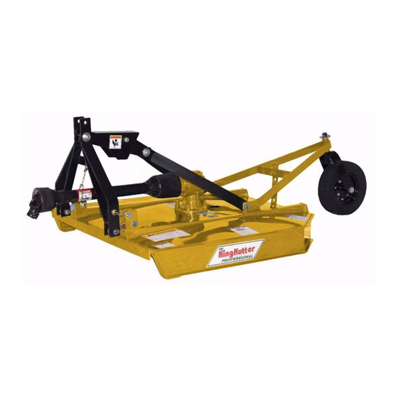
- Page 1 PO Box 1200 305 Commerce Drive Winfield, Alabama 35594 FLEX HITCH ROTARY MOWER OPERATION AND PARTS www.kingkutter.com Part No 999993...
-
Page 3: Customer Information
TO THE PURCHASER This manual contains valuable information about your new King Kutter Mower. It has been carefully prepared to give you helpful suggestions for operating, adjusting, servicing and ordering repair parts. Keep this manual in a convenient place for quick and easy reference. - Page 4 Return the equipment or parts to the authorized King Kutter dealer, from where it was purchased, for ser- vice or replacement of defective parts that are cov- ered by warranty. (The King Kutter Factory may in- spect equipment or parts before warranty claims are honored.) Payment of all costs incurred by the dealer for traveling to ...
-
Page 5: Table Of Contents
CONTENTS ITEM PAGE Safety ................ 6 Assembly Instructions ..........8 Before Putting Into Service ........11 Safety Training ............12 Operational Safety ........... 14 Transportation Safety ..........16 Attaching To Tractor ..........17 Sizing PTO .............. 19 Operating Instructions..........20 Maintenance ............ -
Page 6: Safety
SAFETY READ AND FOLLOW THE INSTRUCTIONS IN THIS MANUAL AND ESPECIALLY IN THE SAFETY SECTION. FAILURE TO DO SO CAN RESULT IN SERIOUS INJURY OR DEATH. TAKE NOTE! THIS SAFETY ALERT SYM- BOL FOUND THROUGHOUT THIS MANUAL IS USED TO CALL YOUR ATTENTION TO THIS SYMBOL MEANS INSTRUCTIONS INVOLVING YOUR PER- ATTENTION! - Page 7 EQUIPMENT SAFETY GUIDELINES Safety of the operator and by standards is one of the main concerns in designing and devel- oping a mower. However, every year accidents occur which could have been avoided by a few seconds of thought and a more careful approach to handling equipment. You, the opera- tor, can avoid many accidents by observing the following precautions and insist those working with you, or for you, follow them.
-
Page 8: Assembly Instructions
FLEX HITCH ROTARY MOWER ASSEMBLY INSTRUCTIONS STEP 1 Place rotary mower on a flat, level surface. (See Figure A) STEP 2 Remove the wired on PTO shaft. Remove the(2) bolts that are on the lift arm lugs, and the bolt holding the pivot shield on. (See arrows Figure C) Place the (3)bolts, the pivot shield and the PTO shaft to the side (See Figure B) you will replace these items as you put the unit together for service. - Page 9 Figure A Figure B Figure D Figure C...
- Page 10 Figure E Figure F Figure G Figure H Figure I...
-
Page 11: Before Putting Into Service
BEFORE PUTTING ROTARY MOWER INTO SERVICE (IMPORTANT-INSTRUCTIONS PRIOR TO START UP) SHIPPED WITH OIL IN GEARBOX SHIPPED WITHOUT GREASE IN GREASE FITTINGS. UNIT MUST BE SERVICED BEFORE USING. Use Multi-Purpose Gear Oil (I.E. S.A.E. 80w/90 or S.A.E. 85w/140 Multi- • purpose gear oil) in Gearbox. -
Page 12: Safety Training
SAFETY TRAINING Safety is a primary concern in the design and manufacture of our product. Un- fortunately, our efforts to provide safe equipment can be wiped out by a single careless act of an operator or bystander. In addition to the design and configuration of equipment, hazard control and ac- cident prevention are dependent upon the awareness, concern, prudence and proper training of personnel involved in the operation, transport, maintenance and storage of this equipment. - Page 13 PREPARTION Never operate the tractor and mower until you have read and completely under- stand this manual, the Tractor Operator’s Manual, and each of the safety mes- sages found on the safety signs on the tractor and mower. Personal protection equipment including hardhat, safety glasses, safety shoes, and gloves are recommended during assembly, installation, operation, adjustment, maintenance, re- pairing, removal, or moving the implement.
-
Page 14: Operational Safety
OPERATIONAL SAFETY The use of this equipment is subject to certain hazards that cannot be protected against by the mechanical means or product design. All operators of this equip- ment must read and understand this entire manual, paying particular attention to safety and operating instructions, prior to using. - Page 15 OPERATIONAL SAFETY continued... Never allow the cutting blade to contact such items. Cut material higher at first, allowing rotary mower to clear hidden objects. Never assume an area is clear. Always Check! Always stop the tractor, disengage PTO, set brake, shut off the tractor engine, remove the ignition key, lower implement to the ground and allow mower blades to come to a complete stop before dismounting tractor.
-
Page 16: Transportation Safety
OPERATIONAL SAFETY continued... Pass rotary mower diagonally through sharp dips and avoid sharp drops to pre- vent “hanging up” tractor and rotary mower. Practice will improve your skills in maneuvering on rough terrain. Always cut down slopes, never across the face. Always check tractor manual for proper use on slopes. -
Page 17: Attaching To Tractor
ATTACHING TO TRACTOR WARNING Never stand between tractor and rotary mower while backing up tractor to the hitch. STEP 1 Attach to tractor's category 1 three point hitch as described in the Tractor's Operator’s Manual. WARNING Failure to install retaining clip on gearbox input shaft would allow driveline to swing freely if bolt is sheared causing possible injury or death. - Page 18 If PTO shaft has been marked for cutting the overlap is the distance measured between the two marks. If the PTO shaft has less than a 6 inch overlap, DO NOT USE. Contact your authorized King Kutter Dealer. NOTE...
-
Page 19: Sizing Pto
SIZING PTO SHAFT STEP 1 Cutting the PTO shaft to length. NOTE: Be sure to cut equal lengths of each PTO shaft section. Clamp end of PTO shaft in a vice and cut off shield where marked. (Figure 1-A & 1-B) Figure 1-A STEP 2 Using cut section of the shield as a... -
Page 20: Operating Instructions
OPERATING INSTRUCTIONS This mower was designed to CUT PASTURE GRASS AND ROUGH AREAS UP TO 1" IN DIAMETER.. Use of your rotary mower to cut any material larger than 1" in diame- ter may damage the mower and void your warranty. PRE-OPERATIONAL ADJUSTMENTS Set tractor's lift control stop at a position that will prevent the PTO shaft from coming in contact with the front edge of the mower when it is at full lift. - Page 21 Note: For best results in heavier cutting conditions adjust the deck so the rear of the mower is approximately 2" higher than the front. This method requires less horse- power and ground speeds of approximately 3-5mph. If finer shredding results are de- sired, adjust the deck to level or slightly lower in the rear.
-
Page 22: Maintenance
MAINTENANCE Periodically check and maintain proper gear oil level. Every 8 hours, wheel fork (s), wheel hub (s), PTO shaft universal joints (2), and PTO telescoping surface. (See Figures M-1 & M-2) NOTE: Use only a grade Type II tube grease. Before each use check to make sure all safety features are installed and work- ing properly. -
Page 23: Maintenance Safety
MAINTENANCE SAFETY Good maintenance is your responsibility. Poor maintenance is an invitation to trouble. Follow good shop practices. Keep service area clean and dry Be sure electrical outlets and tools are properly grounded Use adequate light for the job at hand. ... -
Page 24: Safety Decal's And Locations
SAFETY SIGN LOCATIONS The types of safety signs and locations on the equipment are shown in the illustration below. Good safety requires that you familiarize yourself with the various safety signs, the type of warning and the area, or particular function related to that area, that re- quires your SAFTY AWARENESS REMEMBER: If safety signs have been damaged, removed, become illegible or parts have been replaced without signs, new safety signs must be applied. - Page 28 MODEL NO. DESCRIPTION SN# XXXXXXXXXX...
-
Page 29: Notes
NOTES:... -
Page 30: Replacement Parts
FLEX HITCH KUTTER... - Page 31 Ref. Part Name Part Number Rotary Mower Size 4 Ft. 5 Ft. 6 Ft. 5 Ft. Stainless Tire & Rim /w Hub 403001 403001 403001 403001 Wheel Fork Assembly 403019 403019 403019 403019 Wheel Hub Assembly 191100 191100 191100 191100 A-Frame Assembly 401024 401024...
-
Page 32: Pto Shaft Parts
SHEAR PIN PTO SHAFT Ref. Part Name 147029 147242 147234 Roll Pin Kit (2pk), (1) 8 x 55mm, (1) 8 x 60mm 500131 500131 500131 Male Tube End Yoke 151045 151045 151045 Implement End Yoke 151040 151040 151040 Female Tube End Yoke 151050 151050 151050... - Page 33 SLIP CLUTCH PTO SHAFT Ref. Part Name 147134 Cross Kit 170020 Roll Pin 170120 Female Tube End Yoke 151070 Inner Tube 151092 Slip Clutch Assembly Page 34 Male Tube End Yoke 151065 Outer Tube 151093 Tractor End Yoke 151055 Quick Disconnect Pin 170110 Safety Shield BYPY 124315...
-
Page 34: Slip Clutch Assembly
SLIP CLUTCH ASSEMBLY Ref. Part Name 7” 8” Clutch Spring with Compression Bolts (Pkg 8) 500140 500140 Flanged Yoke 196006 196011 Sleeve 196005 196005 Clutch Plate 196008 196003 Friction Hub 196004 196007 Slip Clutch Lock Bolt 147350 147350 Slip Clutch Liner Plate 196002 195998 Pressure Plate... -
Page 35: Pto Shaft Cover Removal
PTO SHAFTS COVER REMOVAL (Pictures are on next page) BONDIOLI- (BYPY) There are 3 white tabs around the cover as shown in (A in FIG. 1). Take a screwdriver and press against the tabs one at a time with downward angular pressure toward the end of shaft marked (B in FIG. - Page 36 BONDIOLI COVER REMOVAL FIGURE- 1 FIGURE - 2 EUROCARDAN SERIES 4 COVER REMOVAL FIGURE - 3 FIGURE - 4 LA MAGDALENA COVER REMOVAL FIGURE - 5...
- Page 37 PTO SHAFTS COVER REMOVAL EUROCARDAN SERIES 5 There are 2 black tabs around the cover as shown in (B in FIG. 1). Take a flat screwdriver and pry under the tabs one at a time at point (B in FIG. 2) lifting tab over on top of (e-shaped lock).
-
Page 38: Gearbox Parts
40 HP GEARBOX... - Page 39 Ref. Part Name Gearbox Gearbox Gearbox 184000 184005 184010 Snap Ring 106138 106138 106138 Input Seal (NAK 35 x 54 x 10) 156010 156010 156010 Front Cap 129015 129015 129015 Front Cap Gasket 124130 124130 124130 Snap Ring 131031 131031 131031 Snap Ring 131030...
-
Page 40: Warranty
All warranty service will be performed at service centers designated by King Kutter. If King Kutter is unable to repair the product to conform to the warranty after a reasonable number of attempts, King Kutter will provide, at its option, one of the following: (a) a replacement for the product or, (b) a full refund of the purchase price.
Need help?
Do you have a question about the Flex Hitch 999993 and is the answer not in the manual?
Questions and answers