
Related Manuals for Acer Aspire 4738


Summary of Contents for Acer Aspire 4738
- Page 1 Aspire 4738/4738G/4738Z/4738ZG Service Guide Service guide files and updates are available on the ACER/CSD web; for more information, please refer to http://csd.acer.com.tw PRINTED IN TAIWAN...
-
Page 2: Revision History
Revision History Please refer to the table below for the updates made on this service guides. Date Chapter Updates... - Page 3 Copyright Copyright © 2010 by Acer Incorporated. All rights reserved. No part of this publication may be reproduced, transmitted, transcribed, stored in a retrieval system, or translated into any language or computer language, in any form or by any means, electronic, mechanical, magnetic, optical, chemical, manual or otherwise, without the prior written permission of Acer Incorporated.
-
Page 4: Conventions
Conventions The following conventions are used in this manual: Denotes actual messages that appear SCREEN MESSAGES on screen. NOTE Gives bits and pieces of additional information related to the current topic. WARNING Alerts you to any damage that might result from doing or not doing specific actions. - Page 5 DIFFERENT part number code to those given in the FRU list of this printed Service Guide. You MUST use the list provided by your regional Acer office to order FRU parts for repair and service of customer machines.
-
Page 7: Table Of Contents
Your Acer Notebook tour ........ - Page 8 Table of Contents Removing the LCD Module .........69 Removing the Thermal Module .
- Page 9 Aspire 4738 ........
- Page 10 Table of Contents...
-
Page 11: System Specifications
• Up to 2 GB of DDR3 system memory, upgradable to 4 GB using two soDIMM modules Display • 14" HD 1366 x 768 pixel resolution, high-brightness (200-nit) Acer CineCrystal™ LED-backlit TFT • Mercury free, environment friendly • 16:9 aspect ratio... - Page 12 Graphics • Dual independent display support • 16.7 million colors • MPEG-2/DVD decoding • HDMI(TM) (High-Definition Multimedia Interface) with HDCP (High-bandwidth Digital Content Protection) support 4738, 4738Z • Intel(R) HD Graphics with 128 MB of dedicated system memory, supporting Microsoft(R) DirectX(R) 10 •...
-
Page 13: Optical Media Drive
Write: 24X CD-R, 16X CD-RW, 8X DVD-R, 8X DVD+R, 4X DVD-R DL, 4X DVD+R DL, 6X DVD-RW, 8X DVD+RW, 5X DVD-RAM Webcam • Acer Video Conference featuring:· • Acer Crystal Eye 1.3 MP webcam, 1280 x 1024 resolution Wireless and networking • WLAN: • Acer InviLink™ Nplify™ 802.11b/g/n Wi-Fi CERTIFIED™... -
Page 14: Input And Control
Input and control Keyboard • 86-/87-/91-key Acer FineTip keyboard with international language support Touchpad • Multi-gesture touchpad, supporting two-finger scroll, pinch, rotate, flip Media keys • Media control keys (printed on keyboard): play/pause, stop, previous, next, volume up, volume down I/O interface •... - Page 15 Software Productivity • Acer Backup Manager • Acer ePower Management • Acer eRecovery Management • Adobe® Flash® Player 10 • Adobe® Reader® 9.1 • eSobi™ • Microsoft® Office 2010 preloaded (purchase a product key to activate) • Microsoft® Office Starter 2010 •...
-
Page 16: System Block Diagram
System Block Diagram Channel B 64Mb * 16 *4 pc Arrandale rPGA 989 Dual Channel DDR III PCI-E x16 DDRIII-SODIMM1 800/1066 MHZ DDRIII-SODIMM2 DMI(x4) SLG8LV595 X'TAL CLOCK 14.318MHz GENERATOR Display SATA - HDD SATA SATA - ODD PCIE-6 PCI-E x1 USB Port USB-1 MINI CARD... -
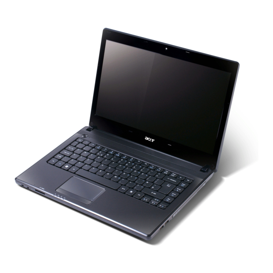
Page 17: Your Acer Notebook Tour
Your Acer Notebook tour Top View Icon Item Description Acer Crystal Eye Web camera for video communication. (only for certain webcam models) Display screen Also called Liquid-Crystal Display (LCD), displays computer output (configuration may vary by model). Power button Turns the computer on and off. -
Page 18: Closed Front View
Icon Item Description Power indicator Indicates the computer's power status. Battery indicator Indicates the computer's battery status. 1. Charging: The light shows amber when the battery is charging. 2. Fully charged: The light shows blue when in AC mode. HDD indicator Indicates when the hard disk drive is active. -
Page 19: Left View
Left View Icon Item Description Kensington lock slot Connects to a Kensington-compatible computer security lock. Note: Wrap the computer security lock cable around an immovable object such as a table or handle of a locked drawer. Insert the lock into the notch and turn the key to secure the lock. -
Page 20: Right View
Right View 3 4 5 Icon Item Description USB 2.0 ports Connect to USB 2.0 devices (e.g., USB mouse, USB camera). Optical drives Internal optical drive; accepts CDs or DVDs. Optical disk access Lights up when the optical drive is indicator active. -
Page 21: Base View
Base View Icon Item Description Battery bay Houses the computer's battery pack. Battery lock Locks the battery in position. Ventilation slots Enable the computer to stay cool, even after prolonged use. Battery release Releases the battery for removal. latch Indicators The computer has several easy-to-read status indicators. -
Page 22: Touch Pad Basics
Touch Pad Basics The following items show you how to use the TouchPad: • Move your finger across the TouchPad (1) to move the cursor. • Press the left (2) and right (3) buttons located beneath the TouchPad to perform selection and execution functions. -
Page 23: Using The Keyboard
Using the Keyboard The keyboard has full-sized keys and an embedded numeric keypad, separate cursor, lock, Windows, function and special keys. Lock Keys and embedded numeric keypad The keyboard has two lock keys which you can toggle on and off. Lock key Description Caps Lock... -
Page 24: Windows Keys
Windows Keys The keyboard has two keys that perform Windows-specific functions. Description Windows key Pressed alone, this key has the same effect as clicking on the Windows Start button; it launches the Start menu. It can also be used with other keys to provide a variety of functions: <... -
Page 25: Hot Keys
Hot Keys The computer employs hotkeys or key combinations to access most of the computer’s controls like screen brightness, volume output and the BIOS utility. To activate hot keys, press and hold the <Fn> key before pressing the other key in the hotkey combination. Hotkey Icon Function... -
Page 26: Hardware Specifications And Configurations
Item Specification CPU type Intel Calpella CPU Package PGA989 Core Logic Intel® Ibex-Peak (HM55) Core Voltage 0~1.5V Processor Specifications (4738, 4738G) Cache Core Acer Item Cores Package Speed Speed Tech Size Voltage Ci3350M 2.26 GHz 350 MHz 32 nm 3 MB PGA988A 0.8-1.4V... - Page 27 CPU Fan True Value Table (TJ90) Fan On (Celsius) Fan Off (Celsius) 2800 3100 3400 3800 4200 Throttling 50%: On= 87°C; OFF=82°C OS shut down at 90°C; H/W shut down at 90°C; VGA Shutdown: 105°C System Memory Item Specification Memory controller Intel Arrandale Memory size 0MB (no on-board memory)
- Page 28 • Suspend to RAM (S3)/Disk (S4) • Various hot-keys for system control • Support SMBIOS 2.3, PCI2.2. • Refer to Acer BIOS specification. • DMI utility for BIOS serial number configurable/asset tag • Support PXE • Support Y2K solution •...
- Page 29 LAN Interface Item Specification Part Name BCM57780 Package 48-pin QFN Features • Requires only a single input power supply: 3.3V. On- board regulators provide all the other required voltages • Supports 25 MHz or 48 MHz external shared-clock source • Loop back modes for diagnostics •...
- Page 30 Speaker Item Specification Vendor Vansonic Enterprise Co., Ltd. Module No. PB2814KN04-9LB Power Rating Normal 1 W, Maximum 1.5 W Output Sound Pressure Level 82 ± 3 db Response FO 700 -/+ 20% Hz Distortion 5% MAX Hard Disk Drive Interface Item Specification Capacity (GB)
- Page 31 Hard Disk Drive Interface (continued) Item Specification Capacity (GB) Vendor & Seagate ST9320310AS Seagate ST9500325AS Model Name HGST HTS545032B9A300 HGST HTS545050B9A300 Toshiba MK3265GSX Toshiba MK5065GSX WD WD3200BPVT-22ZEST0 WD WD5000BEVT-22A0RT0 Bytes per sector Data heads Drive Format Disks 5400 Spindle speed (RPM) Performance Specifications Buffer size...
- Page 32 USB Port Item Specification Chipset USB compliance level EHCI Number of USB port(s) Location 2 on the right, 1 on the left Serial port function control Audio Subsystem Item Specification Audio Controller ALC272X-GR Audio onboard or On board optional Mono or Stereo Mono Resolution •...
- Page 33 HDMI Port Item Specification Compliance level 1.3 compliant Throughput Up to 2.5Gbps per lane (250MHz pixel clock) Number of HDMI port(s) Location Left side PCMCIA Port (Not available in this model) Item Specification PCMCIA controller Supports card type Number of slots Access location Supports ZV (Zoomed Video) port Supports 32-bit CardBus...
- Page 34 Super-Multi Drive Module Item Specification Vendor & model HLDS GT32N Panasonic UJ8A0 name Performance With CD Diskette With DVD With CD Diskette With DVD Diskette specification Diskette Transfer rate Sustained: Sustained: Sustained: Sustained: (Mbps) 3.55 (24x) max. 11.08 (8x) max. 3.55 (24x) max.
- Page 35 Super-Multi Drive Module (continued) Item Specification Vendor & model PLDS DS8A4SH Sony AD7585H name Performance With CD Diskette With DVD With CD Diskette With DVD Diskette Specification Diskette Transfer rate (MB/ Sustained: Sustained: Sustained: Sustained: sec) - CD-ROM inside - DVD-ROM - CD-ROM inside - DVD-ROM inside inside 3700 KB/s...
- Page 36 Super-Multi Drive Module (continued) Item Specification Vendor & model name Toshiba TSL633F Performance Specification With CD Diskette With DVD Diskette Transfer rate (MB/sec) Sustained: Sustained: - CD-ROM/R Read (Mode1) Max - DVD-Single Read Max 3,600 KB/sec 10,800 KB/sec - CD-RW Read (Mode1) Max - DVD-ROM Dual Read Max 3,600 KB/sec 10,800 KB/sec...
- Page 37 I/O Ports Item Specification I/O support ™ • Multi-in-1 card reader (SD , MMC, MS, MS PRO, xD) • Three USB 2.0 ports • External display (VGA) port • Headphone/speaker/line-out jack • Microphone-in jack • Ethernet (RJ-45) port • Modem (RJ-11) port •...
- Page 38 LCD Resolution Resolution 24 bits 30 bits 36 bits 48 bits 640X480p/60Hz 4:3 720X480p/60Hz 4:3 640X480p/60Hz 16:9 1280X720p/60Hz 16:9 1920X1080p/60Hz 16:9 1440X480p/60Hz 4:3 1440X480p/60Hz 16:9 1920X1080p/50Hz 16:9 720X576p/50Hz 4:3 720X576p/50Hz 16:9 1280X720p/50Hz 16:9 1920X1080i/50Hz 16:9 1440X576i/50Hz 4:3 1440X576i/50Hz 16:9 1920X1080p/50Hz 16:9 Item Specification Vendor/model name...
- Page 39 Camera Item Specification Vendor and model Chicony CNF9157 Liteon 09P2SF119 Suyin F1315-S32B-OV01 Type CMOS image sensor with SXGA Interface USB 2.0 Focusing range 31.4cm ~ infinity 32cm ~ infinity 70 mm Dimensions 65.0±0.3 X 8.0±0.1 X 65.0 x 8.0 x 3.53 65 x 8.0 x 3.74 mm 3.69+0.11/-0.2 mm ±0.2mm...
- Page 40 Trusted Platform Module (TPM) (Not available with this model) Item Specification Version Hardware controller System Power Management Item Initial Standby Suspend Hibernate Soft Off Initial On(S0) Standby(S1) Suspend(S3) Hibernate(S4) Soft Off(S5) Mechanical off is a condition where all power except the RTC battery has been removed from the system. 1.
-
Page 41: System Utilities
Chapter 2 System Utilities BIOS Setup Utility The BIOS Setup Utility is a hardware configuration program built into your computer’s BIOS (Basic Input/ Output System). Your computer is already properly configured and optimized, and you do not need to run this utility. However, if you encounter configuration problems, you may need to run Setup. -
Page 42: Information
Information The Information screen displays a summary of your computer hardware information. I n s y d e H 2 0 S e t u p U t i l i t y R e v . 3 . 5 Information Main Security... -
Page 43: Main
Main The Main screen allows the user to set the system time and date as well as enable and disable boot option and recovery. I n s y d e H 2 0 S e t u p U t i l i t y R e v. -
Page 44: Security
Security The Security screen contains parameters that help safeguard and protect your computer from unauthorized use. I n s y d e H 2 0 S e t u p U t i l i t y R e v. 3 . 5 Information Main Security... -
Page 45: Setting A Password
Setting a Password Follow these steps as you set the user or the supervisor password: Use the ↑ and ↓ keys to highlight the Set Supervisor Password parameter and press the Enter key. The Set Supervisor Password box appears: S e t S u p e r v i s o r P a s s w o r d E n t e r N e w P a s s w o r d C o n f i r m N e w P a s s w o r d Type a password in the “Enter New Password”... -
Page 46: Changing A Password
Changing a Password Use the ↑ and ↓ keys to highlight the Set Supervisor Password parameter and press the Enter key. The Set Supervisor Password box appears. S e t S u p e r v i s o r P a s s w o r d E n t e r C u r r e n t P a s s w o r d E n t e r N e w P a s s w o r d C o n f i r m N e w P a s s w o r d... -
Page 47: Boot
Boot This menu allows the user to decide the order of boot devices to load the operating system. Bootable devices includes the USB diskette drives, the onboard hard disk drive and the DVD drive in the module bay. I n s y d e H 2 0 S e t u p U t i l i t y R e v. -
Page 48: Exit
Exit The Exit screen allows you to save or discard any changes you made and quit the BIOS Utility. I n s y d e H 2 0 S e t u p U t i l i t y R e v. -
Page 49: Bios Flash Utility
BIOS Flash Utility The BIOS flash memory update is required for the following conditions: New versions of system programs • New features or options • Restore a BIOS when it becomes corrupted. • DOS Flash Utility Perform the following steps to use the DOS Flash Utility: Copy ZQ5v0.08.exe to a USB stick. -
Page 50: Remove Hdd/Bios Password Utilities
Remove HDD/BIOS Password Utilities This section provides you with details about removing HDD/BIOS password: Remove HDD Password: If you key in the wrong HDD password three times, an error is generated. To reset the HDD password, perform the following steps: After the error is displayed, select the Enter Unlock Password option on the screen. -
Page 51: Removing Bios Passwords
Removing BIOS Passwords: If you key in the wrong Supervisor Password three times, the message System will halt! is displayed on the screen as shown. System will halt! System will halt! Press any key Press any key To reset the BIOS password, Switch to DOS mode and execute ClearSuPw.exe. -
Page 52: Cleaning Bios Passwords
Cleaning BIOS Passwords To clear the password, perform the following steps: From a DOS prompt, Execute clnpwd.exe Press 1 or 2 to clean the desired password shown on the screen. The onscreen message determines whether the function is successful or not. Chapter 2... -
Page 53: Miscellaneous Utilities
Miscellaneous Utilities Using Boot Sequence Selector Boot Sequence Selector allows the boot order to be changes without accessing the BIOS. To use Boot Sequence Selector, perform the following steps: Enter into DOS. Execute BS.exe to display the usage screen. Select the desired boot sequence by entering the corresponding sequence, for example, enter BS2 to change the boot sequence to HDD|CD ROM|LAN|Floppy. - Page 54 Manufacturer (Type1, Offset04h): Acer Product Name (Type1, Offset05h): NS41 xxxxx Serial Number (Type1, Offset07h): 01234567890123456789 UUID String (Type1, Offset08h): xxxxxxxx-xxxx-xxxx-xxxx-xxxxxxxxxxxx Asset Tag (Type3, Offset04h): Acer Asstag Example 2: Write Product Name to EEPROM Input: dmitools /wp Acer Example 3: Write Serial Number to EEPROM...
-
Page 55: Machine Disassembly And Replacement
Chapter 3 Machine Disassembly and Replacement IMPORTANT:The outside housing and color may vary from the mass produced model. This chapter contains step-by-step procedures on how to disassemble the notebook computer for maintenance and troubleshooting. Disassembly Requirements To disassemble the computer, you need the following tools: •... -
Page 56: Pre-Disassembly Instructions
Pre-disassembly Instructions Before proceeding with the disassembly procedure, make sure that you do the following: 1. Turn off the power to the system and all peripherals. 2. Unplug the AC adapter and all power and signal cables from the system. 3. -
Page 57: Disassembly Process
Disassembly Process The disassembly process is divided into the following stages: • External module disassembly • Main unit disassembly • LCD module disassembly The flowcharts provided in the succeeding disassembly sections illustrate the entire disassembly sequence. Observe the order of the sequence to avoid damage to any of the hardware components. For example, if you want to remove the mainboard, you must first remove the keyboard, then disassemble the inside assembly frame in that order. -
Page 58: External Modules Disassembly Process
External Modules Disassembly Process IMPORTANT:The outside housing and color may vary from the mass produced model. External Modules Disassembly Flowchart The flowchart below gives you a graphic representation on the entire disassembly sequence and instructs you on the components that need to be removed during servicing. For example, if you want to remove the mainboard, you must first remove the keyboard, then disassemble the inside assembly frame in that order. -
Page 59: Removing The Battery Pack
Removing the Battery Pack 1. Turn the computer over. Slide the battery lock in the direction shown. 2. Slide and hold the battery release latch to the release position (1), then lift out the battery pack from the main unit (2). NOTE: The battery has been highlighted with a yellow oval as shown in the above image. -
Page 60: Removing The Sd Dummy Card
Removing the SD Dummy Card 1. See “Removing the Battery Pack” on page 51. 2. Push the SD dummy card all the way in to eject it. 3. Pull it out from the slot. Chapter 3... -
Page 61: Removing The Keyboard
Removing the Keyboard NOTE: The model displayed in this service guide may differ in color to the one in your package. 1. See “Removing the Battery Pack” on page 51. 2. Turn the computer over and fully open the lid. There are five (5) securing clips that must be released in order to remove the keyboard. - Page 62 5. Unlock the keyboard FPC and disconnect the cable as shown. Lift the keyboard clear of the chassis. 6. Unlock and disconnect the touchpad FPC from the mainboard: Chapter 3...
-
Page 63: Removing The Odd Module
Removing the ODD Module 1. See “Removing the Battery Pack” on page 51. 2. Remove the one (1) screw securing the ODD module in place. Step Size Quantity Screw Type ODD Module M2.5*6.5 Disassembly 3. Grasp the ODD by the bezel and slide it out of the chassis. Chapter 3... - Page 64 4. Remove the ODD bezel by rotating the top edge downward. 5. Remove the two screws securing the ODD bracket. Step Size Quantity Screw Type ODD Bracket M2.0*3.0 Disassembly 6. Remove the bracket from the ODD. Chapter 3...
-
Page 65: Main Unit Disassembly Process
Main Unit Disassembly Process Main Unit Disassembly Flowchart Screw List Step Screw Quantity Part No. Lower Cover M2.5*6.5 86.ARE07.001 Battery Bay M2.0*3.0 86.ARE07.002 WLAN Module Disassembly M2.0*3.0 86.ARE07.002 USB Module Disassembly M2.5*4.0 86.ARE07.002 HDD Module M2-0.4*2 86.W4107.002 HDD Carrier Disassembly M3.0*3.5 86.N1407.007 LCD Module Disassembly... -
Page 66: Removing The Lower Cover
Removing the Lower Cover 1. See “External Modules Disassembly Process” on page 50. 2. Remove the twenty three (23) securing screws from the lower cover. Step Size Quantity Screw Type Lower Cover M2.5*6.5 (red callout) Battery Bay M2.0*3.0 (green callout) Chapter 3... - Page 67 3. Grasp the ODD bay with one hand while holding the lower cover with the other. Lift the lower cover from the device. Chapter 3...
-
Page 68: Disassembly Overview
Disassembly Overview 1. See “Removing the Lower Cover” on page 58. 2. This section is an overview of the major components of the main unit. 7 6 5 Item Description Item Description RTC battery LVDS cable Bluetooth cable Thermal module WLAN module USB module DIMM module(s) -
Page 69: Removing The Dimm Modules
Removing the DIMM Modules 1. See “Disassembly Overview” on page 60. 2. Push out the release latches on both sides of the DIMM socket to release the DIMM module. 3. Remove the DIMM module. 4. Repeat steps for the second DIMM module if present. Chapter 3... -
Page 70: Removing The Wlan Module
Removing the WLAN Module 1. See “Disassembly Overview” on page 60. 2. Disconnect the two (2) cables from the WLAN board. 3. Remove the one (1) screw. Step Size Quantity Screw Type WLAN Module Disassembly M2.0*3.0 Chapter 3... -
Page 71: Removing The Usb Board
4. Detach and remove the WLAN board from the WLAN socket. Removing the USB Board 1. See “Disassembly Overview” on page 60. 2. Unlock and disconnect the USB FFC from the USB board. Repeat for the mainboard connector. Chapter 3... -
Page 72: Usb Module Disassembly M2.5*4.0
3. Remove the one (1) screw from the USB board. Step Size Quantity Screw Type USB Module M2.5*4.0 Disassembly 4. Lift the USB board upward and away from the chassis. Chapter 3... -
Page 73: Removing The Rtc Battery
Removing the RTC Battery 1. See “Disassembly Overview” on page 60. 2. Disconnect the RTC battery cable from the mainboard. 3. Lift the RTC battery away from the mainboard. NOTE: The RTC battery has been highlighted with the yellow circle as shown in the previous image. Please detach the RTC battery and follow local regulations for disposal. -
Page 74: Removing The Bluetooth Module
Removing the Bluetooth Module 1. See “Removing the Lower Cover” on page 58. 2. Disconnect the Bluetooth cable from the mainboard. 3. Gently pry the Bluetooth module upwards and away from the mainboard. 4. Disconnect the Bluetooth cable from the Bluetooth module. Chapter 3... -
Page 75: Removing The Hdd Module
Removing the HDD Module 1. See “Disassembly Overview” on page 60. 2. Remove the one (1) screw securing the HDD module to the mainboard. Step Size Quantity Screw Type HDD Module M2-0.4*2 3. Using the pull-tab, slide the HDD module in the direction of the arrow to disconnect the interface. Chapter 3... -
Page 76: Hdd Carrier Disassembly M3.0*3.5
4. Remove HDD from the bay. 5. Remove the four (4) screws from the carrier. Step Size Quantity Screw Type HDD Carrier M3.0*3.5 Ni Disassembly 6. Remove the carrier from the HDD. Chapter 3... -
Page 77: Removing The Lcd Module
Removing the LCD Module 1. See “Disassembly Overview” on page 60. 2. Remove the adhesive ground wire from the fan housing. 3. Remove the WLAN antennas from the cable guides. 4. Unlock and disconnect the LVDS cable. Chapter 3... -
Page 78: Lcd Module Disassembly M2.5*6.5
5. Remove the four (4) screws from the left and right hinges. Step Size Quantity Screw Type LCD Module M2.5*6.5 Disassembly 6. Tilt the upper cover upwards slightly (1) and separate it from the LCD module (2). Chapter 3... -
Page 79: Removing The Thermal Module
Removing the Thermal Module 1. See “Disassembly Overview” on page 60. 2. Disconnect the fan cable as shown. 3. Loosen the four (4) captive screws (in numerical order from 1 to 4) and remove the one (1) screw from the fan module. -
Page 80: Removing The Cpu
4. Carefully lift up the thermal module assembly and remove it from the mainboard. IMPORTANT:Place the thermal module on a clean, dry surface when it is not installed. Removing the CPU 1. See “Removing the Thermal Module” on page 71. 2. -
Page 81: Removing The Mainboard
3. Carefully lift the CPU clear of the socket. IMPORTANT:Place the CPU on a clean, dry surface when it is not installed. Removing the Mainboard 1. See “Removing the CPU” on page 72. 2. Remove the adhesive tape securing the speaker cable to the mainboard and disconnect the speaker cable from the mainboard connector. - Page 82 3. Remove the one (1) securing screw from the mainboard. Step Size Quantity Screw Type Mainboard M2.5*4.0 Disassembly 4. Lift the mainboard away the lower cover. Chapter 3...
-
Page 83: Removing The Bluetooth Module
Removing the Bluetooth Module 1. See “Removing the Mainboard” on page 73. 2. Turn the mainboard over and locate the Bluetooth module. 3. Disconnect the Bluetooth cable from the mainboard. Chapter 3... - Page 84 4. Lift the Bluetooth module away from the mainboard. 5. Remove the mylar holder to expose the Bluetooth cable connector. Chapter 3...
- Page 85 6. Disconnect the Bluetooth cable from the Bluetooth module. NOTE: Circuit boards >10 cm² have been highlighted with a yellow rectangle as shown in the previous image. Please detach the Circuit board and follow local regulations for disposal. Chapter 3...
-
Page 86: Lcd Module Disassembly Process
LCD Module Disassembly Process LCD Module Disassembly Flowchart Screw List Step Screw Quantity Part No. LCD Bezel M2.0*5.0 86.T23V7.010 Disassembly LCD Panel M2.5*4.0 86.EDM07.003 Disassembly LCD Hinge M2.0*3.0 86.ARE07.002 Disassembly Chapter 3... -
Page 87: Removing The Lcd Bezel
Removing the LCD Bezel 1. See “Removing the LCD Module” on page 69. 2. Remove the two (2) bezel screws from the LCD module. Step Size Quantity Screw Type LCD Bezel M2.0*5.0 Disassembly 3. Pry the bezel upwards at the top of the LCD module releasing it from the latches. Chapter 3... - Page 88 4. Continue separating the latches along the sides of the bezel towards the hinges. 5. Release the latches at the bottom of the LCD bezel. 6. Lift the bezel clear of the LCD module. Chapter 3...
-
Page 89: Removing The Camera (Ccd) Module
Removing the Camera (CCD) Module 1. See “Removing the LCD Bezel” on page 79. 2. Lift the CCD module from the LCD cover. 3. Disconnect the cable as shown. NOTE: Take care not to damage the cable. Chapter 3... -
Page 90: Removing The Lcd Panel
Removing the LCD Panel 1. See “Removing the LCD Bezel” on page 79. 2. Remove the six (6) securing screws from the LCD panel. Step Size Quantity Screw Type LCD Panel M2.5*4.0 Disassembly 3. Remove the LVDS cable from the cable guides. Chapter 3... -
Page 91: Remove The Lcd Hinges
4. Lift the LCD panel clear of the LCD cover as shown. Remove the LCD Hinges 1. See “Removing the LCD Panel” on page 82. 2. Remove the six (6) screws, three on each side. Separate the hinges from the LCD panel. Step Size Quantity... -
Page 92: Removing The Lvds Cable
Removing the LVDS Cable 1. See “Removing the LCD Panel” on page 82. 2. Detach the CCD cable from the back of the LCD panel. 3. Remove the yellow tape securing the LVDS cable. 4. Starting from the top, remove the clear mylar covering and disconnect the LVDS cable from the LCD panel. Chapter 3... -
Page 93: Removing The Wlan Antennas
Removing the WLAN Antennas 1. See “Removing the LCD Panel” on page 82. 2. Remove the black and white WLAN antennas from the cable guides. 3. Remove the black antenna cable from the LCD cover. Repeat for the white antenna. Chapter 3... -
Page 94: Lcd Module Assembly Process
LCD Module Assembly Process Replacing the WLAN Antennas 1. Place the black antenna cable onto the LCD cover as shown. Repeat for the white antenna. 2. Place the black and white WLAN antennas into the cable guides as shown. Chapter 3... -
Page 95: Replacing The Lvds Cable
Replacing the LVDS Cable 1. Turn the LCD panel face down on a non-abrasive, clean surface. Ensure the panel face does not get damaged. Connect the LVDS cable to the LCD panel. Place the clear mylar tape over the connector and press firmly. 2. -
Page 96: Replacing The Lcd Hinges
Replacing the LCD Hinges 1. See “Removing the LCD Panel” on page 82. 2. Replace the six (6) screws, three on each side to secure the hinges. Step Size Quantity Screw Type LCD Hinge M2.0*3.0 Assembly Chapter 3... -
Page 97: Removing The Lcd Panel
Removing the LCD Panel 1. Place the LCD panel on the LCD cover as shown. 2. Place the LVDS cable into the cable guides. Chapter 3... - Page 98 3. Replace the six (6) securing screws to secure the LCD panel. Step Size Quantity Screw Type LCD Panel M2.5*4.0 Assembly Chapter 3...
-
Page 99: Replacing The Camera (Ccd) Module
Replacing the Camera (CCD) Module 1. Connect the CCD cable as shown. NOTE: Take care not to damage the cable. 2. Place the CCD module onto the LCD cover. Apply gentle pressure to fix the adhesive. Chapter 3... -
Page 100: Replacing The Lcd Bezel
Replacing the LCD Bezel 1. Place the bezel hinge covers over the hinges. 2. Ensure the LVDS and WLAN antenna cable bundle are exiting the left hinge as shown. 3. Apply pressure to snap the latches together. Chapter 3... - Page 101 4. Apply pressure along the bottom of the bezel to attach the latches. 5. Apply pressure along the sides of the bezel to attach the latches. 6. Apply pressure along the top of the bezel to attach the latches. Chapter 3...
- Page 102 7. Replace the two (2) bezel screws. Step Size Quantity Screw Type LCD Bezel M2.0*5.0 Assembly Chapter 3...
-
Page 103: Main Unit Assembly Process
Main Unit Assembly Process Replacing the Bluetooth Module 1. Connect the Bluetooth cable to the Bluetooth module. 2. Attach mylar holder to the Bluetooth cable connector. Chapter 3... - Page 104 3. Place the Bluetooth module onto the mainboard. 4. Connect the Bluetooth cable to the mainboard connector. Chapter 3...
-
Page 105: Replacing The Mainboard
Replacing the Mainboard 1. Place the mainboard onto the upper cover. 2. Replace the one (1) screw to secure the mainboard to the upper cover. Step Size Quantity Screw Type Mainboard M2.5*4.0 Assembly Chapter 3... - Page 106 3. Secure the speaker cable to the mainboard using the adhesive tape connected to the cable. 4. Connect the speaker cable to the mainboard. Chapter 3...
-
Page 107: Replacing The Cpu
Replacing the CPU IMPORTANT:The CPU has a Pin1 locator (1) that must be positioned corresponding to the marker (2) on the CPU socket. 1. Place the CPU into the CPU socket as shown, taking note of the Pin1 locator. 2. Using a slotted screw driver, rotate the CPU locking screw 180° clockwise as shown to secure it in the package. -
Page 108: Replacing The Thermal Module
Replacing the Thermal Module IMPORTANT:Apply a suitable thermal grease and ensure all heat pads are in place before replacing the thermal module The following thermal materials are approved for use: • Thermal grease compound • Eapus PSX-D • Thermal pad •... - Page 109 5. Connect the fan cable as shown. Chapter 3...
-
Page 110: Replacing The Lcd Module
Replacing the LCD Module 1. Place the upper cover onto the LCD module and lower into place. Lower the hinges so they are flush with the hinge plates on the upper cover. 2. Replace the four (4) screws to secure the left and right hinges. Step Size Quantity... - Page 111 3. Connect and lock the LVDS cable. 4. Place the WLAN antenna bundle into the cable guides around the fan module. 5. Place the adhesive ground wire attached to the WLAN antenna cable bundle onto the fan housing. Chapter 3...
-
Page 112: Replacing The Hdd Module
Replacing the HDD Module 1. Place the carrier onto the HDD. 2. Replace the four (4) screws to secure the HDD carrier. Step Size Quantity Screw Type HDD Carrier M3.0*3.5 Ni Assembly 3. Place HDD in the HDD bay. Chapter 3... - Page 113 4. Using the pull-tab, slide the HDD module in the direction of the arrow to connect the interface. 5. Replace the one (1) screw to secure the HDD module to the upper cover. Step Size Quantity Screw Type HDD Module M2-0.4*2 Assembly Chapter 3...
-
Page 114: Replacing The Rtc Battery
Replacing the RTC Battery 1. Place the RTC battery onto the mainboard. 2. Connect the RTC battery cable to the mainboard connector. Chapter 3... -
Page 115: Replacing The Usb Board
Replacing the USB Board 1. Place the USB board onto the chassis. 2. Replace one (1) screw to secure the USB board. Step Size Quantity Screw Type USB Board M2.5*4.0 Assembly 3. Connect and lock the USB FFC to the USB board. Repeat for the mainboard connector. Chapter 3... -
Page 116: Replacing The Wlan Module
Replacing the WLAN Module 1. Insert the WLAN board into the WLAN socket. 2. Replace the one (1) screw. Step Size Quantity Screw Type WLAN Board M2.0*3.0 Assembly Chapter 3... - Page 117 3. Connect the two (2) antenna cables to the WLAN board as shown. NOTE: Cable placement is as follows: black (Main) to connector J1, white (AUX) to connector J2. Chapter 3...
-
Page 118: Replacing The Dimm Modules
Replacing the DIMM Modules 1. Insert the DIMM module into the DIMM connector. 2. Press down to lock the DIMM module in place. 3. Repeat steps 1 and 2 for the second DIMM module if present. Chapter 3... -
Page 119: Replacing The Lower Cover
Replacing the Lower Cover 1. Place the lower cover onto the device. 2. Replace the twenty three (23) screws to secure the lower cover to the device. Step Size Quantity Screw Type Lower Cover M2.5*6.5 (red callout) Battery Bay M2.0*3.0 (green callout) Chapter 3... -
Page 120: External Module Assembly Process
External Module Assembly Process Replacing the ODD Module 1. Place the ODD bracket onto the ODD module and replace the two (2) screws to secure it. Step Size Quantity Screw Type ODD Bracket M2.0*3.0 Assembly 2. Press the bezel into the tray, bottom edge first, to secure it to the ODD module. Chapter 3... - Page 121 3. Push the ODD module into the ODD bay until it is flush with the casing. 4. Replace the one (1) screw to secure the module. Step Size Quantity Screw Type ODD Module M2.5*6.5 Assembly Chapter 3...
-
Page 122: Replacing The Keyboard
Replacing the Keyboard 1. Connect and lock the touchpad FFC to the mainboard connector. 2. Place the keyboard face down on the upper cover. Connect the keyboard FPC to the mainboard and secure the locking latch. 3. Turn the keyboard over and slide the front edge into the upper cover, ensuring that the four locating tabs are correctly seated. - Page 123 4. Press down as indicated to secure the keyboard in place. Chapter 3...
-
Page 124: Replacing The Sd Dummy Card
Replacing the SD dummy card 1. Insert the SD dummy card into the slot and push until the card clicks into place and is flush with the casing. Replacing the Battery Pack 1. Insert the battery pack and press down. 2. -
Page 125: Troubleshooting
Common Problems Use the following procedure as a guide for computer problems. NOTE: The diagnostic tests are intended to test only Acer products. Non-Acer products, prototype cards, or modified options can give false errors and invalid system responses. Obtain the failing symptoms in as much detail as possible. -
Page 126: Power On Issue
Power On Issue If the system doesn’t power on, perform the following actions one at a time to correct the problem. Do not replace a non-defective FRU: Start Check Swap AC/Battery AC/Battery Swap M/B Computer Shutsdown Intermittently If the system powers off at intervals, perform the following actions one at a time to correct the problem. Check the power cable is properly connected to the computer and the electrical outlet. -
Page 127: No Display Issue
No Display Issue If the Display doesn’t work, perform the following actions one at a time to correct the problem. Do not replace a non-defective FRU: START LCD module Replace LCD panel/ goto no power LCD cable Power On? trouble shooting step Ext. -
Page 128: Abnormal Video Display
Abnormal Video Display If video displays abnormally, perform the following actions one at a time to correct the problem. Reboot the computer. If permanent vertical/horizontal lines or dark spots display in the same location, the LCD is faulty and should be replaced. See “Disassembly Process” on page 49. If extensive pixel damage is present (different colored spots in the same locations on the screen), the LCD is faulty and should be replaced. -
Page 129: Lcd Failure
LCD Failure If the LCD fails, perform the following actions one at a time to correct the problem. Do not replace a non- defective FRU: Start Check MB LCD Reassemble connector and Re-plug LCD cable Check LCD Swap module? LCD cable /LCD panel Swap M/B Chapter 4... -
Page 130: Built-In Keyboard Failure
Built-In Keyboard Failure If the built-in Keyboard fails, perform the following actions one at a time to correct the problem. Do not replace a non-defective FRU: Touch Pad Failure If the TouchPad doesn’t work, perform the following actions one at a time to correct the problem. Do not replace a non-defective FRU: Start Re-assemble the... -
Page 131: Internal Speaker Failure
Internal Speaker Failure If the internal Speakers fail, perform the following actions one at a time to correct the problem. Do not replace a non-defective FRU: Start Re-assemble the Check M/B SPK SPK cable to M/B cable Swap M/B Internal Microphone Failure If the internal Microphone fails, perform the following actions one at a time to correct the problem. -
Page 132: Usb Failure
USB Failure If the internal USB module fails, perform the following actions one at a time to correct the problem. Do not replace a non-defective FRU: Start Re-assemble the Check USB/B to M/B cable USB/B cable to M/B Swap USB/B and Check USB/B USB cable Swap M/B... -
Page 133: Sound Problems
Sound Problems If sound problems are experienced, perform the following actions one at a time to correct the problem. Reboot the computer. Navigate to Start Control Panel System and Maintenance System Device Manager. Check the Device Manager to determine that: •... -
Page 134: Hdd Not Operating Correctly
HDD Not Operating Correctly If the HDD does not operate correctly, perform the following actions one at a time to correct the problem. Disconnect all external devices. Run a complete virus scan using up-to-date software to ensure the computer is virus free. Run the Windows 7 Startup Repair Utility: insert the Windows 7 Operating System DVD in the ODD and restart the computer. -
Page 135: Odd Failure
ODD Failure If the ODD fails, perform the following actions one at a time to correct the problem. Do not replace a non- defective FRU: ODD Not Operating Correctly If the ODD exhibits any of the following symptoms it may be faulty: •... - Page 136 Double-click lDE ATA/ATAPI controllers. If a device displays a down arrow, right-click on the device and click Enable. Double-click DVD/CD-ROM drives. If the device displays a down arrow, right-click on the device and click Enable. Check that there are no yellow exclamation marks against the items in lDE ATA/ATAPI controllers. If a device has an exclamation mark, right-click on the device and uninstall and reinstall the driver.
- Page 137 Double-click IDE ATA/ATAPI controllers, then right-click ATA Device 0. Click Properties and select the Advanced Settings tab. Ensure that the Enable DMA box is checked and click OK. Repeat for the other ATA Devices shown if applicable. Drive Not Detected If Windows cannot detect the drive, perform the following actions one at a time to correct the problem.
-
Page 138: Wireless Function Failure
Wireless Function Failure If the WLAN fails, perform the following actions one at a time to correct the problem. Do not replace a non- defective FRU: Thermal Unit Failure If the Thermal Unit fails, perform the following actions one at a time to correct the problem. Do not replace a non-defective FRU: Chapter 4... -
Page 139: External Mouse Failure
External Mouse Failure If an external Mouse fails, perform the following actions one at a time to correct the problem. Try an alternative mouse. If the mouse uses a wireless connection, insert new batteries and confirm there is a good connection. See the mouse user manual. -
Page 140: Intermittent Problems
Issue” on page 118.): Power-off the computer. Visually check them for damage. If any problems are found, replace the FRU. Remove or disconnect all of the following devices: • Non-Acer devices • Printer, mouse, and other external devices • Battery pack •... -
Page 141: Post Codes
Post Codes These tables describe the POST codes and descriptions during the POST. Post Code Range Phase POST Code Range 0x01 - 0x0F 0x70 - 0x9F 0x40 - 0x6F 0x10 - 0x3F 0xA0 - 0xBF 0xC0 - 0xCF 0x51 – 0x55 0xE1 –... - Page 142 Functionality Name (Include\ Post Phase Description PostCode.h) Code PEI_PROGRAM_CLOCK_GEN Clock Generator Initialization PEI_IGD_EARLY_INITIAL Internal Graphic device early Initialization PEI_HECI_INIT HECI Initialization PEI_WATCHDOG_INIT Watchdog timer Initialization PEI_MEMORY_INIT Memory Initial for Normal boot. PEI_MEMORY_INIT_FOR_CRISIS Memory Initial for Crisis Recovery PEI_MEMORY_INSTALL Simple Memory test PEI_TXTPEI TXT function early Initialization PEI_SWITCH_STACK...
- Page 143 Functionality Name (Include\ Phase PostCode Description PostCode.h) DXE_SMM_CONTROLER_INIT Setup SMM Control service DXE_LEGACY_INTERRUPT Setup Legacy Interrupt service DXE_RELOCATE_SMBASE Relocate SMM BASE DXE_FIRST_SMI SMI test DXE_VTD_INIT VTD Initial DXE_BEFORE_CSM16_INIT Legacy BIOS Initialization DXE_AFTER_CSM16_INIT Legacy interrupt function Initialization DXE_LOAD_ACPI_TABLE ACPI Table Initialization DXE_SB_DISPATCH Setup SB SMM Dispatcher service...
- Page 144 Functionality Name (Include\ Post Phase Description PostCode.h) Code BDS_END_OF_BOOT_SELECTION End of boot selection BDS_ENTER_SETUP Enter Setup Menu BDS_ENTER_BOOT_MANAGER Enter Boot manager BDS_BOOT_DEVICE_SELECT Try to boot system to OS BDS_EFI64_SHADOW_ALL_LEGACY_RO Shadow Misc Option ROM BDS_ACPI_S3SAVE Save S3 resume required data in BDS_READY_TO_BOOT_EVENT Last Chipset initial before boot to BDS_GO_LEGACY_BOOT...
- Page 145 Post Functionality Name (Include\ PostCode.h) Phase Description Code S3_BEFORE_MP_INIT Multi-processor initial dur- ing S3 resume S3_BEFORE_RESTORE_ACPI_CALLBACK Start to restore system con- figuration in SMM S3_AFTER_RESTORE_ACPI_CALLBACK Restore system configura- tion in SMM complete S3_GO_TO_FACS_WAKING_VECTOR Back to OS ACPI Functions POST Code Table Post Functionality Name (Include\ PostCode.h) Phase...
- Page 146 Chapter 4...
-
Page 147: Jumper And Connector Locations
Chapter 5 Jumper and Connector Locations Top View Item Description Item Description PWR BUTTON LED5 WIFI LED VCORE PWM IC LEFT BUTTON HDMI LEVEL SHIFT IC RIGHT BUTTON VGFX PWM IC SYSTEM (3V/5V) PWM IC GLAN IC 1.05V PWM IC CODEC IC 32.768KHZ CRYSTAL INTERNAL MIC... -
Page 148: Bottom View
Bottom View Item Description Item Description DC JACK CN12 HDD CONN CPU SOCKET CN10 USB BOARD CONN CRT CONN BIOS ROM GLAN CONN RTC CONN TRANSFORMER ODD CONN CN11 HDMI CONN CLOCK GENERATOR CN14 USB CONN CN18 EXT MIC CONN CN17 EXT HP CONN BATTERY CONN... -
Page 149: Clearing Password Check And Bios Recovery
This section provides you with the standard operating procedures of clearing password and BIOS recovery for the Aspire 4738/4738G/4738Z/4738ZG. The machine provides one Hardware Open Gap on main board for clearing password check, and one Hotkey for enabling BIOS Recovery. -
Page 150: Clear Cmos Jumper
Clear CMOS Jumper Item Description J1/J2 Clear CMOS Jumper Chapter 5... -
Page 151: Bios Recovery By Crisis Disk
BIOS Recovery by Crisis Disk BIOS Recovery Boot Block: BIOS Recovery Boot Block is a special block of BIOS. It is used to boot up the system with minimum BIOS initialization. Users can enable this feature to restore the BIOS firmware to a successful one once the previous BIOS flashing process failed. - Page 152 Chapter 5...
-
Page 153: Fru (Field Replaceable Unit) List
Guide. For ACER AUTHORIZED SERVICE PROVIDERS, your Acer office may have a DIFFERENT part number code from those given in the FRU list of this printed Service Guide. You MUST use the local FRU list provided by your regional Acer office to order FRU parts for repair and service of customer machines. -
Page 154: Exploded Diagrams
Exploded Diagrams LCD Assembly Description Acer P/N Left hinge 33.R6Z07.004 LVDS cable assy 50.R6Z07.004 Camera AM.21400.067 LCD bezel 60.R6Z07.010 Right hinge 33.R6Z07.005 LCD Panel LK.14008.004 LCD cover 60.R6Z07.009 Chapter 6... -
Page 155: Chassis Assembly
Chassis Assembly Description Acer P/N Description Acer P/N Bluetooth module BH.21100.006 Upper cover 60.R6Z07.001 Mainboard MB.R5X06.001 6M.R6W07.001 Dummy card 42.PSR07.002 KH.16001.045 Thermal module 60.R6W07.001 USB board 55.R6W07.001 Base assy 60.R6Z07.007 USB FFC 50.R6Z07.001 Keyboard KB.I140A.204 Battery BT.00603.111 Chapter 6... -
Page 156: Fru List
FRU List Category Description ADAPTER Adapter DELTA 65W 19V 1.7x5.5x11 Yellow ADP- AP.06501.026 65JH DB A, LV5 LED LF Adapter DELTA 65W 19V 1.7x5.5x11 Yellow ADP- AP.06501.033 65VH BA, LV5, Low profile LED LF Adapter LITE-ON 65W 19V 1.7x5.5x11 Yellow PA- AP.06503.024 1650-22AC LV5 LED LF Adapter LITE-ON 65W 19V 1.7x5.5x11 Yellow PA-... - Page 157 Category Description Foxconn Bluetooth BRM 2046 BT2.1 (T60H928.33 BH.21100.006 Ver.3/PCB V015) HSF Foxconn Bluetooth BRM 2046 BT3.0 (T60H928.33) f/ BH.21100.008 w:861 Foxconn Bluetooth ATH AR3011 BH.21100.005 Foxconn Bluetooth ATH AR3011 (BT3.0) BH.21100.009 Foxconn Bluetooth BRM 2070 (T77H114.01) BH.21100.007 Foxconn Bluetooth BRM 2070 (T77H114.01) BT 3.0 BH.21100.010 USB BOARD 55.R6W07.001...
- Page 158 Category Description FFC- TP TO MB 50.R6Z07.003 SPEAKER 23.R6Z07.001 CASE/COVER/BRACKET ASSEMBLY UPPER CASE W/ SPK,TP, TP FFC - RED 60.R6Z07.003 UPPER CASE W/O SPK,TP,TP FFC - RED 60.R6Z07.006 TOUCH PAD 56.R6Z07.001 FFC- TP TO MB 50.R6Z07.003 SPEAKER 23.R6Z07.001 CASE/COVER/BRACKET ASSEMBLY LOWER CASE 60.R6Z07.007 HINGE SUPPORT BRACKET FOR UPPER CASE...
- Page 159 Category Description DVD RW DRIVE DVD/RW SUPER MULTI SATA MODULE 6M.R6W07.001 ODD TOSHIBA Super-Multi DRIVE 12.7mm Tray DL KU.00801.040 8X TS-L633F LF W/O bezel SATA (HF + Windows 7) ODD HLDS Super-Multi DRIVE 12.7mm Tray DL 8X KU.0080D.055 GT32N (R5-2) LF W/O bezel SATA with Renesas solution + PCC LD (HF + Windows 7) ODD SONY Super-Multi DRIVE 12.7mm Tray DL 8X KU.0080E.027...
- Page 160 Keyboard ACER AC4T_A10B AC4T 87KS Black KB.I140A.205 Belgium Texture Keyboard ACER AC4T_A10B AC4T 87KS Black KB.I140A.206 Brazilian Portuguese Texture Keyboard ACER AC4T_A10B AC4T 87KS Black CZ/ KB.I140A.207 SK Texture Keyboard ACER AC4T_A10B AC4T 86KS Black KB.I140A.208 Chinese Texture Keyboard ACER AC4T_A10B AC4T 87KS Black KB.I140A.209...
- Page 161 Keyboard ACER AC4T_A10B AC4T 87KS Black KB.I140A.220 Portuguese Texture Keyboard ACER AC4T_A10B AC4T 86KS Black KB.I140A.221 Russian Texture Keyboard ACER AC4T_A10B AC4T 87KS Black SLO/ KB.I140A.222 CRO Texture Keyboard ACER AC4T_A10B AC4T 87KS Black KB.I140A.223 Spanish Texture Keyboard ACER AC4T_A10B AC4T 87KS Black KB.I140A.224...
- Page 162 Category Description LED LCD LPL 14" WXGA Glare LP140WH1-TLA2 LF LK.14008.004 220nit 8ms 500:1 LED LCD SAMSUNG 14" WXGA Glare LTN140AT01- LK.14006.011 G03 LF 220nit 8ms 500:1 LED LCD CMI 14" WXGA Glare BT140GW01 V6 LF LK.1400D.008 220nit 8ms 600:1 LCD COVER W/ ANT - IMR BLACK 60.R6Z07.009 ANTENNA - WIMAX...
- Page 163 Category Description LED LCD LPL 14" WXGA Glare LP140WH1-TLA2 LF LK.14008.004 220nit 8ms 500:1 LED LCD SAMSUNG 14" WXGA Glare LTN140AT01- LK.14006.011 G03 LF 220nit 8ms 500:1 LED LCD CMI 14" WXGA Glare BT140GW01 V6 LF LK.1400D.008 220nit 8ms 600:1 LCD COVER W/ ANT - IMR BROWN 60.R6Z07.011 ANTENNA - WIMAX...
- Page 164 Category Description LED LCD LPL 14" WXGA Glare LP140WH1-TLA2 LF LK.14008.004 220nit 8ms 500:1 LED LCD SAMSUNG 14" WXGA Glare LTN140AT01- LK.14006.011 G03 LF 220nit 8ms 500:1 LED LCD CMI 14" WXGA Glare BT140GW01 V6 LF LK.1400D.008 220nit 8ms 600:1 LCD COVER W/ ANT - IMR RED 60.R6Z07.012 ANTENNA - WIMAX...
- Page 165 Category Description MEMORY Memory KINGSTON SO-DIMM DDRIII 1333 1GB KN.1GB07.004 ACR128X64D3S1333C9 LF 128*8 0.065um Memory ELPIDA SO-DIMM DDRIII 1333 1GB KN.1GB09.015 EBJ10UE8BDS0-DJ-F LF 128*8 0.065um Memory SAMSUNG SO-DIMM DDRIII 1333 1GB KN.1GB0B.035 M471B2873FHS-CH9 LF 128*8 46nm Memory HYNIX SO-DIMM DDRIII 1333 1GB KN.1GB0G.026 HMT112S6TFR8C-H9 LF 128*8 0.055um Memory KINGSTON SO-DIMM DDRIII 1333 2GB...
-
Page 166: Screw List
Screw List Category Description SCREW SCREW M2.5*6.5-I(BZN(NYLOK-RED) 86.ARE07.001 SCREW M2.5*4.0-I(BKAG)(NYLOK)IRON 86.PSR07.001 SCREW M2.0*3.0-I(BKAG)(NYLOK IRON 86.ARE07.002 SCREW M2.5*4.0-I(BUWZN)(NYLON PATCH)IRON 86.EDM07.003 SCREW M2.0*5-I(NI)(NYLOK) 86.T23V7.010 SCREW M3*0.5+3.5I 86.N1407.007 SCREW M2-0.4*2-I(BNI)(NYLOK)IRON 86.W4107.002 SCREW M2.0*3.95-I(BNI)(NYLOK) 86.R6Z07.002 SCREW M2.5*4.0-I(NI)(NYLOK) 86.R6Z07.001 Chapter 6... - Page 167 Chapter 6...
-
Page 168: Model Definition And Configuration
Appendix A Model Definition and Configuration Aspire 4738 Model Country Acer Part No Description AS4738- Malaysia LX.R5X0C.001 AS4738-351G32Mnkk LINPUS MAMY1 351G32Mnkk UMACkk_3 1*1G/320/BT/6L2.2/2R/ CB_bgn_1.3C_HG_XS11 AS4738- GCTWN S2.R5X02.001 AS4738-352G25Mnkk W7HP64ASWW1 352G25Mnkk MC UMACkk_3 2*1G/250/BT/6L2.2/2R/ CB_bgn_1.3C_HG_ES61 AS4738- Malaysia LX.R5X02.005 AS4738-352G32Mnkk EM 352G32Mnkk W7HP64EMASMY1 MC UMACkk_3 1*2G/320/BT/6L2.2/2R/... - Page 169 Model Country Acer Part No Description AS4738- Indonesia LX.R7L0C.002 AS4738-371G50Mnrr LINPUS MAID1 371G50Mnrr UMACrr_3 1*1G/500_L/6L2.2/2R/ CB_bgn_1.3C_HG_ID32 AS4738- Singapore LX.R7K02.004 AS4738-372G32Mncc W7HP64ASSG1 372G32Mncc MC UMACcc_3 1*2G/320/BT/6L2.2/2R/ CB_bgn_1.3C_HG_ES61 AS4738- Singapore LX.R7K02.005 AS4738-372G32Mncc W7HP64ASSG1 372G32Mncc MC UMACcc_3 1*2G/320_5.4k_4k/BT/ 6L2.2/2R/CB_bgn_1.3C_HG_ZH31 AS4738- Vietnam LX.R7K0C.003 AS4738-372G32Mncc LINPUS MAVN1 372G32Mncc UMACcc_3 1*2G/320/BT/6L2.2/2R/...
- Page 170 Model Country Acer Part No Description AS4738- Indonesia LX.R7K01.001 AS4738-372G50Mncc EM 372G50Mncc W7HB64EMASID1 MC UMACcc_3 1*2G/500_L/BT/6L2.2/2R/ CB_bgn_1.3C_HG_ID21 AS4738- Thailand LX.R7K02.001 AS4738-372G50Mncc EM 372G50Mncc W7HP64EMASTH4 MC UMACcc_3 1*2G/500_L/BT/6L2.2/2R/ CB_bgn_1.3C_HG_ES61 AS4738- Thailand LX.R7K02.002 AS4738-372G50Mncc EM 372G50Mncc W7HP64EMASTH3 MC UMACcc_3 1*2G/500_L/BT/6L2.2/2R/ CB_bgn_1.3C_HG_ES61 AS4738- Thailand LX.R7K02.003...
- Page 171 Model Country Acer Part No Description AS4738- ACLA-Spain LX.R5X02.010 AS4738-373G32Mnkk EM 373G32Mnkk W7HP64EMASEA3 MC UMACkk_3 2G+1G/320/6L2.2/2R/ CB_bgn_1.3C_HG_ES51 AS4738- ACLA-Spain LX.R5X02.011 AS4738-373G32Mnkk EM 373G32Mnkk W7HP64EMASEA1 MC UMACkk_3 2G+1G/320_5.4k_4k/6L2.2/2R/ CB_bgn_1.3C_HG_ES51 AS4738- ACLA-Spain LX.R5X02.012 AS4738-373G32Mnkk EM 373G32Mnkk W7HP64EMASEA4 MC UMACkk_3 2G+1G/320_5.4k_4k/6L2.2/2R/ CB_bgn_1.3C_HG_EN31 AS4738- ACLA-Spain LX.R5X0C.014...
- Page 172 Model Country Acer Part No Description AS4738- Chile LX.R5X02.017 AS4738-373G50Mnkk EM 373G50Mnkk W7HP64EMASCL3 MC UMACkk_3 2G+1G/500_L/6L2.2/2R/ CB_bgn_1.3C_HG_ES51 AS4738- ACLA-Spain LX.R5X02.018 AS4738-374G32Mnkk EM 374G32Mnkk W7HP64EMASEA3 MC UMACkk_3 2*2G/320/6L2.2/2R/ CB_bgn_1.3C_HG_ES51 AS4738- ACLA-Spain LX.R5X02.019 AS4738-374G32Mnkk EM 374G32Mnkk W7HP64EMASEA1 MC UMACkk_3 2*2G/320_5.4k_4k/6L2.2/2R/ CB_bgn_1.3C_HG_ES51 AS4738- ACLA-Spain LX.R5X02.020...
- Page 173 Model Country Acer Part No Description AS4738- ACLA-Spain LX.R5X02.028 AS4738-5464G50Mnkk EM 5464G50Mnkk W7HP64EMASEA4 MC UMACkk_3 2*2G/500_L/6L2.2/2R/ CB_bgn_1.3C_HG_EN31 AS4738- Chile LX.R5X02.029 AS4738-5464G50Mnkk EM 5464G50Mnkk W7HP64EMASCL3 MC UMACkk_3 2*2G/500_L/6L2.2/2R/ CB_bgn_1.3C_HG_ES51 Model Country Acer Part No BOM Name Chip AS4738- Malaysia LX.R5X0C.001 AS4738_UMACkk_3...
- Page 174 Model Country Acer Part No BOM Name Chip AS4738- Chile LX.R5X01.008 AS4738_UMACkk_3 Ci3370M 372G32Mnkk AS4738- Singapore LX.R5X02.030 AS4738_UMACkk_3 Ci3370M 372G32Mnkk AS4738- Singapore LX.R5X02.031 AS4738_UMACkk_3 Ci3370M 372G32Mnkk AS4738- Singapore LX.R5X0C.011 AS4738_UMACkk_3 Ci3370M 372G32Mnkk AS4738- Thailand LX.R5X02.009 AS4738_UMACkk_3 Ci3370M 372G32Mnkk AS4738- Thailand LX.R5X0C.005...
- Page 175 Model Country Acer Part No BOM Name Chip AS4738- ACLA- LX.R5X01.004 AS4738_UMACkk_3 Ci3370M 373G32Mnkk Spain AS4738- ACLA- LX.R5X02.010 AS4738_UMACkk_3 Ci3370M 373G32Mnkk Spain AS4738- ACLA- LX.R5X02.011 AS4738_UMACkk_3 Ci3370M 373G32Mnkk Spain AS4738- ACLA- LX.R5X02.012 AS4738_UMACkk_3 Ci3370M 373G32Mnkk Spain AS4738- ACLA- LX.R5X0C.014 AS4738_UMACkk_3...
- Page 176 Model Country Acer Part No BOM Name Chip AS4738- ACLA- LX.R5X02.024 AS4738_UMACkk_3 Ci5460M 5463G32Mnkk Spain AS4738- Chile LX.R5X02.025 AS4738_UMACkk_3 Ci5460M 5463G32Mnkk AS4738- GCTWN S2.R7K02.001 AS4738_UMACcc_3 Ci5460M 5464G25Mncc AS4738- ACLA- LX.R5X02.026 AS4738_UMACkk_3 Ci5460M 5464G50Mnkk Spain AS4738- ACLA- LX.R5X02.027 AS4738_UMACkk_3 Ci5460M 5464G50Mnkk...
- Page 177 Model Country Acer Part No VRAM 1 Memory 1 Memory 2 AS4738- Singapore LX.R7K02.005 SO2GBIII10 372G32Mncc AS4738- Vietnam LX.R7K0C.003 SO2GBIII10 372G32Mncc AS4738- ACLA-Spain LX.R5X01.006 SO2GBIII10 372G32Mnkk AS4738- ACLA-Spain LX.R5X01.007 SO2GBIII10 372G32Mnkk AS4738- Chile LX.R5X01.008 SO2GBIII10 372G32Mnkk AS4738- Singapore LX.R5X02.030 SO2GBIII10...
- Page 178 Model Country Acer Part No VRAM 1 Memory 1 Memory 2 AS4738- Indonesia LX.R7L01.001 SO2GBIII10 372G50Mnrr AS4738- Middle East LX.R7K01.002 SO2GBIII10 SO1GBIII10 373G32Mncc AS4738- ACLA-Spain LX.R5X01.003 SO2GBIII10 SO1GBIII10 373G32Mnkk AS4738- ACLA-Spain LX.R5X01.004 SO2GBIII10 SO1GBIII10 373G32Mnkk AS4738- ACLA-Spain LX.R5X02.010 SO2GBIII10 SO1GBIII10...
- Page 179 Model Country Acer Part No VRAM 1 Memory 1 Memory 2 AS4738- ACLA-Spain LX.R5X02.022 SO2GBIII10 SO1GBIII10 5463G32Mnkk AS4738- ACLA-Spain LX.R5X02.023 SO2GBIII10 SO1GBIII10 5463G32Mnkk AS4738- ACLA-Spain LX.R5X02.024 SO2GBIII10 SO1GBIII10 5463G32Mnkk AS4738- Chile LX.R5X02.025 SO2GBIII10 SO1GBIII10 5463G32Mnkk AS4738- GCTWN S2.R7K02.001 SO2GBIII10 SO2GBIII10...
- Page 180 Model Country Acer Part No HDD 1(GB) Bluetooth AS4738- Singapore LX.R7K02.004 N320GB5.4KS_4K NSM8XS BT 3.0 372G32Mncc AS4738- Singapore LX.R7K02.005 N320GB5.4KS_4K NSM8XS BT 3.0 372G32Mncc AS4738- Vietnam LX.R7K0C.003 N320GB5.4KS NSM8XS BT 2.1 372G32Mncc AS4738- ACLA-Spain LX.R5X01.006 N320GB5.4KS_4K NSM8XS 372G32Mnkk AS4738- ACLA-Spain LX.R5X01.007...
- Page 181 Model Country Acer Part No HDD 1(GB) Bluetooth AS4738- Thailand LX.R5X0C.010 N500GB5.4KS NSM8XS BT 2.1 372G50Mnkk AS4738- Indonesia LX.R7L01.001 N500GB5.4KS NSM8XS BT 3.0 372G50Mnrr AS4738- Middle East LX.R7K01.002 N320GB5.4KS_4K NSM8XS BT 3.0 373G32Mncc AS4738- ACLA-Spain LX.R5X01.003 N320GB5.4KS_4K NSM8XS 373G32Mnkk AS4738- ACLA-Spain LX.R5X01.004...
-
Page 182: Aspire 4738G
Model Country Acer Part No HDD 1(GB) Bluetooth AS4738- Singapore LX.R5X02.007 N500GB5.4KS NSM8XS BT 3.0 382G50Mnkk AS4738- ACLA-Spain LX.R5X02.022 N320GB5.4KS_4K NSM8XS 5463G32Mnkk AS4738- ACLA-Spain LX.R5X02.023 N320GB5.4KS_4K NSM8XS 5463G32Mnkk AS4738- ACLA-Spain LX.R5X02.024 N320GB5.4KS_4K NSM8XS 5463G32Mnkk AS4738- Chile LX.R5X02.025 N320GB5.4KS_4K NSM8XS 5463G32Mnkk... - Page 183 Model Country Acer Part No Description AS4738G- Indonesia LX.R5W02.002 AS4738G-372G32Mnkk EM 372G32Mnkk W7HP64EMASID1 MC PARK_XT512Ckk_3V3 1*2G/320/BT/ 6L2.2/2R/CB_bgn_1.3C_HG_ID21 AS4738G- Indonesia LX.R5W0C.001 AS4738G-372G32Mnkk LINPUSAID1 372G32Mnkk PARK_XT512Ckk_3V3 1*2G/320/BT/ 6L2.2/2R/CB_bgn_1.3C_HG_ID22 AS4738G- Thailand LX.R5W0C.002 AS4738G-372G32Mnkk LINPUSATH4 372G32Mnkk PARK_XT512Ckk_3V3 1*2G/320/BT/ 6L2.2/2R/CB_bgn_1.3C_HG_ES61 AS4738G- Thailand LX.R5W0C.003 AS4738G-372G32Mnkk LINPUSATH3...
- Page 184 Model Country Acer Part No Description AS4738G- Indonesia LX.R7E02.002 AS4738G-372G50Mnrr EM 372G50Mnrr W7HP64EMASID1 MC PARK_XT512Crr_3V3 1*2G/500_L/ BT/6L2.2/2R/CB_bgn_1.3C_HG_ID21 AS4738G- Indonesia LX.R7E0C.002 AS4738G-372G50Mnrr LINPUSAID1 372G50Mnrr PARK_XT512Crr_3V3 1*2G/500_L/ BT/6L2.2/2R/CB_bgn_1.3C_HG_ID22 AS4738G- GCTWN S2.R6W02.001 AS4738G-373G32Mncc 373G32Mncc W7HP64ASWW1 MC PARK_XT512Ccc_3V3 2G+1G/320/ BT/6L2.2/2R/CB_bgn_1.3C_HG_ES61 AS4738G- CHINA China LX.R5W0C.010...
- Page 185 Model Country Acer Part No BOM Name VGA Chip AS4738G- Indonesia LX.R6W0C.002 AS4738G_PARK_XT Ci3370M PARK_XT 372G50Mncc 512Ccc_3V3 AS4738G- Indonesia LX.R5W02.004 AS4738G_PARK_XT Ci3370M PARK_XT 372G50Mnkk 512Ckk_3V3 AS4738G- Indonesia LX.R5W0C.008 AS4738G_PARK_XT Ci3370M PARK_XT 372G50Mnkk 512Ckk_3V3 AS4738G- Malaysia LX.R5W02.003 AS4738G_PARK_XT Ci3370M PARK_XT 372G50Mnkk...
- Page 186 Model Country Acer Part No VRAM 1 Memory 1 Memory 2 AS4738G- Indonesia LX.R7E02.001 512M-DDR3 SO2GBIII10 372G32Mnrr (64*16*4) AS4738G- Indonesia LX.R7E0C.001 512M-DDR3 SO2GBIII10 372G32Mnrr (64*16*4) AS4738G- Indonesia LX.R6W02.002 512M-DDR3 SO2GBIII10 372G50Mncc (64*16*4) AS4738G- Indonesia LX.R6W0C.002 512M-DDR3 SO2GBIII10 372G50Mncc (64*16*4) AS4738G- Indonesia LX.R5W02.004...
-
Page 187: Aspire 4738Z
Bluetoot Model Country Acer Part No HDD 1(GB) AS4738G- Indonesia LX.R5W0C.001 N320GB5.4KS NSM8XS BT 2.1 372G32Mnkk AS4738G- Thailand LX.R5W0C.002 N320GB5.4KS NSM8XS BT 2.1 372G32Mnkk AS4738G- Thailand LX.R5W0C.003 N320GB5.4KS NSM8XS BT 2.1 372G32Mnkk AS4738G- Thailand LX.R5W0C.004 N320GB5.4KS NSM8XS BT 2.1 372G32Mnkk... - Page 188 Model Country Acer Part No Description AS4738Z- Indonesia LX.R6T0C.001 AS4738Z-P611G32Mnkk LINPUS P611G32Mnkk MAID1 UMACkk_3 1*1G/320/6L2.2/2R/ CB_bgn_1.3C_HG_ID32 AS4738Z- Malaysia LX.R6T0C.005 AS4738Z-P611G32Mnkk LINPUS P611G32Mnkk MAMY1 UMACkk_3 1*1G/320/BT/6L2.2/ 2R/CB_bgn_1.3C_HG_XS11 AS4738Z- Singapore LX.R6T0C.029 AS4738Z-P611G32Mnkk LINPUS P611G32Mnkk MASG1 UMACkk_3 1*1G/320/BT/6L2.2/ 2R/CB_bgn_1.3C_HG_XS11 AS4738Z- Thailand LX.R6T0C.006 AS4738Z-P611G32Mnkk LINPUS P611G32Mnkk MATH1 UMACkk_3 1*1G/320/BT/6L2.2/...
- Page 189 Model Country Acer Part No Description AS4738Z- Philippines LX.R7H0C.005 AS4738Z-P612G32Mncc LINPUS P612G32Mncc MAPH1 UMACcc_3 1*2G/320/BT/6L2.2/ 2R/CB_bgn_1.3C_HG_XS11 AS4738Z- Singapore LX.R7H02.003 AS4738Z-P612G32Mncc P612G32Mncc W7HP64ASSG1 MC UMACcc_3 1*2G/ 320/BT/6L2.2/2R/ CB_bgn_1.3C_HG_ES61 AS4738Z- Singapore LX.R7H02.004 AS4738Z-P612G32Mncc P612G32Mncc W7HP64ASSG1 MC UMACcc_3 1*2G/ 320_5.4k_4k/BT/6L2.2/2R/ CB_bgn_1.3C_HG_ZH31 AS4738Z- Vietnam LX.R7H0C.008...
- Page 190 Model Country Acer Part No Description AS4738Z- EMEA Middle East LX.R6T01.002 AS4738Z-P612G32Mnkk EM P612G32Mnkk W7HB64EMASME2 MC UMACkk_3 1*2G/320/BT/6L2.2/2R/ CB_bgn_1.3C_HG_ARA1 AS4738Z- Philippines LX.R6T0C.004 AS4738Z-P612G32Mnkk LINPUS P612G32Mnkk MAPH1 UMACkk_3 1*2G/320/BT/6L2.2/ 2R/CB_bgn_1.3C_HG_XS11 AS4738Z- Singapore LX.R6T02.005 AS4738Z-P612G32Mnkk P612G32Mnkk W7HP64ASSG1 MC UMACkk_3 1*2G/ 320/BT/6L2.2/2R/ CB_bgn_1.3C_HG_ES61...
- Page 191 Model Country Acer Part No Description AS4738Z- India LX.R7J0C.007 AS4738Z-P612G50Mnrr LINPUS MAIN1 P612G50Mnrr UMACrr_3 1*2G/500_L/BT/6L2.2/2R/ CB_bgn_1.3C_HG_XS11 AS4738Z- Singapore LX.R7J0C.006 AS4738Z-P612G50Mnrr LINPUS P612G50Mnrr MASG1 UMACrr_3 1*2G/500_L/BT/ 6L2.2/2R/CB_bgn_1.3C_HG_XS11 AS4738Z- Singapore LX.R7H0C.003 AS4738Z-P613G32Mncc LINPUS P613G32Mncc MASG1 UMACcc_3 2G+1G/320/BT/ 6L2.2/2R/CB_bgn_1.3C_HG_XS11 AS4738Z- ACLA-Spain LX.R6T01.006 AS4738Z-P613G32Mnkk EM...
- Page 192 Model Country Acer Part No Description AS4738Z- ACLA-Spain LX.R6T02.019 AS4738Z-P614G32Mnkk EM P614G32Mnkk W7HP64EMASEA1 MC UMACkk_3 2*2G/320_5.4k_4k/6L2.2/2R/ CB_bgn_1.3C_HG_ES51 AS4738Z- ACLA-Spain LX.R6T02.020 AS4738Z-P614G32Mnkk EM P614G32Mnkk W7HP64EMASEA4 MC UMACkk_3 2*2G/320_5.4k_4k/6L2.2/2R/ CB_bgn_1.3C_HG_EN31 AS4738Z- Chile LX.R6T02.021 AS4738Z-P614G32Mnkk EM P614G32Mnkk W7HP64EMASCL3 MC UMACkk_3 2*2G/320_5.4k_4k/6L2.2/2R/ CB_bgn_1.3C_HG_ES51 AS4738Z- ACLA-Spain LX.R6T02.010...
- Page 193 Model Country Acer Part No Description AS4738Z- Thailand LX.R6T0C.014 AS4738Z-P621G50Mnkk LINPUS P621G50Mnkk MATH3 UMACkk_3 1*1G/500_L/BT/ 6L2.2/2R/CB_bgn_1.3C_HG_XS11 AS4738Z- Singapore LX.R7H02.005 AS4738Z-P622G25Mncc P622G25Mncc W7HP64ASSG1 MC UMACcc_3 1*2G/ 250/BT/6L2.2/2R/ CB_bgn_1.3C_HG_ES61 AS4738Z- Singapore LX.R7H02.006 AS4738Z-P622G25Mncc P622G25Mncc W7HP64ASSG1 MC UMACcc_3 1*2G/ 250/BT/6L2.2/2R/ CB_bgn_1.3C_HG_ZH31 AS4738Z- Singapore LX.R6T02.003...
- Page 194 Model Country Acer Part No BOM Name Chip AS4738Z- Indonesia LX.R7H0C.001 AS4738Z_UMACcc_3 PMDP6100 P611G32Mncc AS4738Z- Singapore LX.R7H0C.002 AS4738Z_UMACcc_3 PMDP6100 P611G32Mncc AS4738Z- Indonesia LX.R6T0C.001 AS4738Z_UMACkk_3 PMDP6100 P611G32Mnkk AS4738Z- Malaysia LX.R6T0C.005 AS4738Z_UMACkk_3 PMDP6100 P611G32Mnkk AS4738Z- Singapore LX.R6T0C.029 AS4738Z_UMACkk_3 PMDP6100 P611G32Mnkk AS4738Z- Thailand LX.R6T0C.006...
- Page 195 Model Country Acer Part No BOM Name Chip AS4738Z- ACLA- LX.R6T08.001 AS4738Z_UMACkk_3 PMDP6100 P612G32Mnkk Spain AS4738Z- ACLA- LX.R6T08.002 AS4738Z_UMACkk_3 PMDP6100 P612G32Mnkk Spain AS4738Z- Chile LX.R6T01.005 AS4738Z_UMACkk_3 PMDP6100 P612G32Mnkk AS4738Z- Chile LX.R6T08.003 AS4738Z_UMACkk_3 PMDP6100 P612G32Mnkk AS4738Z- China LX.R6T0C.002 AS4738Z_UMACkk_3 PMDP6100 P612G32Mnkk...
- Page 196 Model Country Acer Part No BOM Name Chip AS4738Z- India LX.R7J0C.007 AS4738Z_UMACrr_3 PMDP6100 P612G50Mnrr AS4738Z- Singapore LX.R7J0C.006 AS4738Z_UMACrr_3 PMDP6100 P612G50Mnrr AS4738Z- Singapore LX.R7H0C.003 AS4738Z_UMACcc_3 PMDP6100 P613G32Mncc AS4738Z- ACLA- LX.R6T01.006 AS4738Z_UMACkk_3 PMDP6100 P613G32Mnkk Spain AS4738Z- ACLA- LX.R6T01.007 AS4738Z_UMACkk_3 PMDP6100 P613G32Mnkk Spain...
- Page 197 Model Country Acer Part No BOM Name Chip AS4738Z- Thailand LX.R6T0C.018 AS4738Z_UMACkk_3 PMDP6200 P621G32Mnkk AS4738Z- Thailand LX.R6T0C.019 AS4738Z_UMACkk_3 PMDP6200 P621G32Mnkk AS4738Z- Thailand LX.R6T0C.020 AS4738Z_UMACkk_3 PMDP6200 P621G32Mnkk AS4738Z- Thailand LX.R6T0C.012 AS4738Z_UMACkk_3 PMDP6200 P621G50Mnkk AS4738Z- Thailand LX.R6T0C.013 AS4738Z_UMACkk_3 PMDP6200 P621G50Mnkk AS4738Z- Thailand LX.R6T0C.014...
- Page 198 Model Country Acer Part No VRAM 1 Memory 1 Memory 2 AS4738Z- Malaysia LX.R6T0C.005 SO1GBIII10 P611G32Mnkk AS4738Z- Singapore LX.R6T0C.029 SO1GBIII10 P611G32Mnkk AS4738Z- Thailand LX.R6T0C.006 SO1GBIII10 P611G32Mnkk AS4738Z- Thailand LX.R6T0C.007 SO1GBIII10 P611G32Mnkk AS4738Z- Thailand LX.R6T0C.008 SO1GBIII10 P611G32Mnkk AS4738Z- Indonesia LX.R7J0C.001 SO1GBIII10...
- Page 199 Model Country Acer Part No VRAM 1 Memory 1 Memory 2 AS4738Z- China LX.R6T0C.002 SO2GBIII10 P612G32Mnkk AS4738Z- Indonesia LX.R6T01.001 SO2GBIII10 P612G32Mnkk AS4738Z- Malaysia LX.R6T02.009 SO2GBIII10 P612G32Mnkk AS4738Z- Malaysia LX.R6T0C.024 SO2GBIII10 P612G32Mnkk AS4738Z- Middle East LX.R6T01.002 SO2GBIII10 P612G32Mnkk AS4738Z- Philippines LX.R6T0C.004...
- Page 200 Model Country Acer Part No VRAM 1 Memory 1 Memory 2 AS4738Z- ACLA-Spain LX.R6T01.008 SO2GBIII10 SO1GBIII10 P613G32Mnkk AS4738Z- ACLA-Spain LX.R6T02.014 SO2GBIII10 SO1GBIII10 P613G32Mnkk AS4738Z- ACLA-Spain LX.R6T02.015 SO2GBIII10 SO1GBIII10 P613G32Mnkk AS4738Z- ACLA-Spain LX.R6T02.016 SO2GBIII10 SO1GBIII10 P613G32Mnkk AS4738Z- ACLA-Spain LX.R6T0C.025 SO2GBIII10 SO1GBIII10...
- Page 201 Model Country Acer Part No VRAM 1 Memory 1 Memory 2 AS4738Z- Singapore LX.R7H02.005 SO2GBIII10 P622G25Mncc AS4738Z- Singapore LX.R7H02.006 SO2GBIII10 P622G25Mncc AS4738Z- Singapore LX.R6T02.003 SO2GBIII10 P622G25Mnkk AS4738Z- Singapore LX.R6T02.004 SO2GBIII10 P622G25Mnkk AS4738Z- Philippines LX.R7H0C.006 SO2GBIII10 P622G32Mncc AS4738Z- Singapore LX.R7H02.001 SO2GBIII10...
- Page 202 Model Country Acer Part No HDD 1(GB) Bluetooth AS4738Z- Thailand LX.R6T0C.010 N500GB5.4KS NSM8XS BT 2.1 P611G50Mnkk AS4738Z- Thailand LX.R6T0C.011 N500GB5.4KS NSM8XS BT 2.1 P611G50Mnkk AS4738Z- Hong Kong LX.R7H02.007 N250GB5.4KS NSM8XS BT 3.0 P612G25Mncc AS4738Z- Singapore LX.R6T02.007 N250GB5.4KS NSM8XS BT 3.0...
- Page 203 Model Country Acer Part No HDD 1(GB) Bluetooth AS4738Z- Singapore LX.R6T02.006 N320GB5.4KS NSM8XS BT 3.0 P612G32Mnkk AS4738Z- Singapore LX.R6T0C.028 N320GB5.4KS NSM8XS BT 2.1 P612G32Mnkk AS4738Z- Thailand LX.R6T0C.015 N320GB5.4KS NSM8XS BT 2.1 P612G32Mnkk AS4738Z- Thailand LX.R6T0C.016 N320GB5.4KS NSM8XS BT 2.1 P612G32Mnkk...
- Page 204 Model Country Acer Part No HDD 1(GB) Bluetooth AS4738Z- Chile LX.R6T02.017 N320GB5.4KS_4K NSM8XS P613G32Mnkk AS4738Z- ACLA- LX.R6T02.018 N320GB5.4KS_4K NSM8XS P614G32Mnkk Spain AS4738Z- ACLA- LX.R6T02.019 N320GB5.4KS_4K NSM8XS P614G32Mnkk Spain AS4738Z- ACLA- LX.R6T02.020 N320GB5.4KS_4K NSM8XS P614G32Mnkk Spain AS4738Z- Chile LX.R6T02.021 N320GB5.4KS_4K NSM8XS...
-
Page 205: Aspire 4738Zg
Model Country Acer Part No HDD 1(GB) Bluetooth AS4738Z- Philippines LX.R6T0C.003 N320GB5.4KS NSM8XS BT 2.1 P622G32Mnkk AS4738Z- Singapore LX.R6T02.001 N320GB5.4KS NSM8XS BT 3.0 P622G32Mnkk AS4738Z- Singapore LX.R6T02.002 N320GB5.4KS NSM8XS BT 3.0 P622G32Mnkk AS4738Z- Thailand LX.R6T0C.021 N320GB5.4KS NSM8XS BT 2.1 P622G32Mnkk... - Page 206 Model Country Acer Part No Description AS4738ZG- Philippines LX.R7F0C.002 AS4738ZG-P612G32Mncc P612G32Mncc LINPUSAPH1 PARK_XT512Ccc_3V3 1*2G/320/BT/6L2.2/2R/ CB_bgn_1.3C_HG_EN11 AS4738ZG- CHINA China LX.R650C.001 AS4738ZG-P612G32Mnkk P612G32Mnkk LINPUSACN1 PARK_XT512Ckk_3V3 1*2G/320/6L2.2/2R/ CB_bgn_1.3C_HG_EN91 AS4738ZG- GCTWN LX.R6502.001 AS4738ZG-P612G32Mnkk P612G32Mnkk W7HP64ASTW1 MC PARK_XT512Ckk_3V3 1*2G/320/BT/ 6L2.2/2R/CB_bgn_1.3C_HG_TC11 AS4738ZG- Philippines LX.R650C.003 AS4738ZG-P612G32Mnkk P612G32Mnkk LINPUSAPH1 PARK_XT512Ckk_3V3 1*2G/320/BT/6L2.2/2R/...
- Page 207 Model Country Acer Part No Description AS4738ZG- Thailand LX.R650C.018 AS4738ZG-P621G32Mnkk P621G32Mnkk LINPUSATH1 PARK_XT512Ckk_3V3 1*1G/320/BT/6L2.2/2R/ CB_bgn_1.3C_HG_TH51 AS4738ZG- Thailand LX.R650C.019 AS4738ZG-P621G50Mnkk P621G50Mnkk LINPUSATH4 PARK_XT512Ckk_3V3 1*1G/500_L/BT/6L2.2/2R/ CB_bgn_1.3C_HG_ES61 AS4738ZG- Thailand LX.R650C.020 AS4738ZG-P621G50Mnkk P621G50Mnkk LINPUSATH3 PARK_XT512Ckk_3V3 1*1G/500_L/BT/6L2.2/2R/ CB_bgn_1.3C_HG_EN11 AS4738ZG- Thailand LX.R650C.021 AS4738ZG-P621G50Mnkk P621G50Mnkk LINPUSATH1 PARK_XT512Ckk_3V3 1*1G/500_L/BT/6L2.2/2R/...
- Page 208 Model Country Acer Part No BOM Name VGA Chip AS4738ZG- Thailand LX.R650C.008 AS4738ZG_PARK_XT5 PMDP6100 PARK_XT P611G50Mnkk 12Ckk_3V3 AS4738ZG- China LX.R7F0C.003 AS4738ZG_PARK_XT5 PMDP6100 PARK_XT P612G32Mncc 12Ccc_3V3 AS4738ZG- Hong LX.R7F02.001 AS4738ZG_PARK_XT5 PMDP6100 PARK_XT P612G32Mncc Kong 12Ccc_3V3 AS4738ZG- Philippin LX.R7F0C.002 AS4738ZG_PARK_XT5 PMDP6100 PARK_XT...
- Page 209 Model Country Acer Part No BOM Name VGA Chip AS4738ZG- Thailand LX.R650C.009 AS4738ZG_PARK_XT5 PMDP6200 PARK_XT P622G50Mnkk 12Ckk_3V3 Acer Model Country VRAM 1 Memory 1 Memory 2 HDD 1(GB) Part No AS4738ZG- Thailand LX.R65 512M- SO1GBIII10 N320GB5.4KS P611G32Mnkk 0C.013 DDR3 (64*16*4)
- Page 210 Acer Model Country VRAM 1 Memory 1 Memory 2 HDD 1(GB) Part No AS4738ZG- Thailand LX.R65 512M- SO2GBIII10 N500GB5.4KS P612G50Mnkk 0C.012 DDR3 (64*16*4) AS4738ZG- GCTWN S2.R7F 512M- SO2GBIII10 SO2GBIII10 N500GB5.4KS P614G50Mncc 02.001 DDR3 (64*16*4) AS4738ZG- GCTWN S2.R7G 512M- SO2GBIII10 SO2GBIII10 N500GB5.4KS...
-
Page 211: Aspire 4742
Aspire 4742 Model Country Acer Part No Description AS4742- Vietnam LX.R5X02.002 AS4742-352G50Mnkk EM 352G50Mnkk W7HP64EMASVN1 MC UMACkk_3 1*2G/500_L/BT/6L2.2/2R/ CB_bgn_1.3C_HG_ES61 AS4742- S2.R5X0C.001 AS4742-352G50Mnkk LINPUSAWW1 352G50Mnkk UMACkk_3 1*2G/500_L/6L2.2/2R/ CB_bgn_1.3C_HG_EN11 Model Country Acer Part No BOM Name VGA Chip AS4742- Vietnam LX.R5X02.002 AS4738_U... - Page 212 Model Country Acer Part No HDD 1(GB) Bluetooth AS4742G- S2.R5W02.001 N750GB5.4KS NSM8XS BT 3.0 356G75Mnkk AS4742G- S2.R6502.001 N640GB5.4KS NSM8XS BT 3.0 358G64Mnkk Appendix A...
-
Page 213: Test Compatible Components
Appendix B Test Compatible Components This computer’s compatibility is tested and verified by Acer’s internal testing department. All of its system ® ® functions are tested under Windows 7 with backwards compatibility to Windows Refer to the following lists for components, adapter cards, and peripherals which have passed these tests. - Page 214 Vendor Type Description INTEL Ci3370M CPU Intel Core i3 370M PGA 2.4G 35W K-0 KC.37K01.DMP TJ90, VT INTEL Ci3380M CPU Intel Core i3 380M PGA 2.53G 35W K-0 KC.38K01.DMP TJ90, VT INTEL Ci5460M CPU Intel Core i5 460M PGA 2.53G 35W K-0 KC.46K01.DMP INTEL Ci5560M...
- Page 215 KH.75008.009 22HXZT1, ML375M, 4K drive SATA 8MB LF F/ W:01.01A01 Keyboard ACER AC4T_A10B Keyboard ACER AC4T_A10B AC4T Internal KB.I140A.202 14 Standard Black Y2010 Acer Legend Texture Broadcom BCM57780 Broadcom BCM57780 NI.22400.047 NLED14WXGAG LED LCD AUO 14" WXGA Glare B140XW01 LK.14005.010...
- Page 216 Appendix B...
-
Page 217: Online Support Information
This section describes online technical support services available to help you repair your Acer Systems. If you are a distributor, dealer, ASP or TPM, please refer your technical queries to your local Acer branch office. Acer Branch Offices and Regional Business Units may access our website. However some information sources will require a user i.d. - Page 218 Appendix C...
-
Page 219: Index
Index 51, 116 67, 104 Battery Pack Hard Disk Drive Module BIOS HDTV Switch Failure ROM type Hibernation mode vendor hotkey Version Hot Keys 33–41 BIOS Utility Advanced Boot Intermittent Problems Exit Navigating Internal Microphone Failure Power Internal Speaker Failure Save and Exit Security System Security... - Page 220 55, 112 optical drive module Panel Bottom left Power On Failure 65, 106 RTC Battery 52, 116 SD Card System Block Diagram Test Compatible Components 71, 100 Thermal Module Thermal Unit Failure TouchPad Failure Troubleshooting Built-in KB Failure EasyTouch Buttons HDTV Switch Internal Microphone Internal Speakers...
Need help?
Do you have a question about the Aspire 4738 and is the answer not in the manual?
Questions and answers