
Related Manuals for Carbolite P1


Summary of Contents for Carbolite P1
-
Page 1: Operating Instructions
Operating Instructions Temperature Controller Type 3216 P1 P5 English MC18-GB – v1.04... - Page 2 MC18-GB – v1.04...
-
Page 3: Table Of Contents
3216 Controller Contents INTRODUCTION TO THE CONTROLLER AND MANUAL SING ANUAL PID C ONTROL BASIC OPERATION ONTROLLER AYOUT ISPLAY QUICK START GUIDE PERATION AS A SIMPLE CONTROLLER HANGING THE OINT SING HE CONTROLLER NDERSTANDING EVELS SETTING UP THE CONTROLLER AXIMUM UTPUT OWER ETTING... -
Page 4: Introduction To The Controller And Manual
Introduction 1 Introduction to the Controller and Manual Using This Manual This manual aims to explain how to set up and operate the Eurotherm 3216 series of controllers; it must be read in conjunction with the product main manual. Due to the complex nature of furnace or oven control the use of technical terms throughout this manual is unavoidable. -
Page 5: Basic Operation
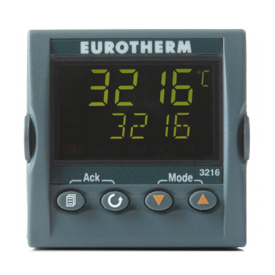
Basic Operation 2 Basic Operation Controller Layout (Home Display) Power Output Measured Indicator Temperature Setpoint Temperature Alarm Hold Indicator Indicator Remote Run Indicator Indicator (When configured) Scroll Key Page Key Scroll Key Up Key Down Key Keys The Page key is used to access level 2 when held down Page Key for 3 seconds. -
Page 6: Quick Start Guide
Quick Start Guide 3 Quick Start Guide Operation as a simple controller When switched on, the controller goes through a short test routine and then shows the measured temperature (PV = Process Value) in the upper part of the display, and below it, the set temperature (Set Point). - Page 7 Quick Start Guide When level 2 operations have been completed, the supervisor must return to Level 1 either manually or by ‘power cycling’, there is no time out function. To Return to Level 1 1. Press and hold the page Key to select LEu 1 2.
-
Page 8: Setting Up The Controller
Programming 4 Setting up the controller Before using the controller (or during its lifetime) certain parameters may have to be set, depending on specific requirements. To do this the controller must be set to supervisor level (Level 2) see section 3.4 Maximum Output Power Setting until the display shows OP.HI <Output High>. -
Page 9: Customer Calibration
Programming until the display shows. TEXT <ENABLE/DISABLE SCROLLING TEXT> Press Scroll to select ON or OFF Use the Up Down Customer Calibration The 3216 series of controllers are calibrated for life at manufacture, there may however be sensor or other system errors, which affect the accuracy of the measured temperature. Customer calibration can be used to compensate for these errors. -
Page 10: Holdback
5 Programming Creating a Program Programs can be created in level 1 or level 2 of the 3216 P1 and 3216P5. Each program contains 8 Ramp/Dwell pairs. Note: A currently active program cannot be altered. - Page 11 Programming Ramp Units until the display shows RAMP.U <Ramp Units>: Use the Up Press scroll Down select the Ramp Units of Hour, Min or Seconds. Dwell Units until the display shows DWEL.U <Dwell Units>: Use the Up Press Scroll Down select the Dwell Units of Hour or Min.
-
Page 12: Running A Program
Programming Running a Program to display PROG <PROGRAM NUMBER> select the If using the 3216P5 controller Press Scroll required Program Number before running a Program. Table below shows the key presses to run a program Operation Action Indication To RUN a program Press and quickly Indicator –... - Page 13 Programming Time Remaining until the display shows T.REMN <TIME REMAINING>. This shows the dwell Press scroll time remaining for the current segment. There is no value for “Ramp Time Remaining” therefore when the program is ramping the dwell time set will be shown and will only begin to count down when the ramp has finished.
-
Page 14: Program Example
Program Example Program Example The following sequence of entries creates and runs the program shown graphically below. Press Scroll until the display shows RAMP.U <SP RAMP UNITS>. Select MIN. Press Scroll until the display shows DWELL.U <DWELL UNITS>. Select MIN. Press Scroll until the display shows RMP.1 <RAMP RATE 1>. -
Page 15: Options
To reveal or hide parameters in the controller it is necessary to go into configuration modes and enter a security codes. Please consult Carbolite. Digital Communications – RS232 If the RS232 option is supplied, then the furnace is fitted with one subminiature D-socket connected to the controller communications (comms) module. -
Page 16: Comms Address
Options Comms Address Typically the comms address is set to 1, but this can be changed. In the case of RS485 and multiple instruments it is necessary to set different addresses. To change the address value access the level 2 list. In level 2 press the scroll key until the ADDR (ADDRESS) parameter is displayed. -
Page 17: 3216P1 & 3216P5
U dwel.U rmp.1 h. b ack A2. # If Configured t.sp1 rmp. 1 A3. # dwel. 1 t. s p1 A4. # Through to dwel.1 op.hi rmp.8 LD. A MP t.sp8 LK. A MP Do not raise the power limit dwel. -
Page 18: Controller Fault
Controller Fault 8 Controller Fault Fault Code Diagnostic Table Error Code Explanation Actions Replace the Furnace or Oven S.br Temperature sensor failure Temperature Sensor 9 Glossary of Terms Process Value (PV) The actual temperature of the furnace or oven. °C The target temperature the furnace or oven is trying to Setpoint (SP) °C... - Page 19 Notes MC18-GB – v1.04...
- Page 20 Int: +44 1433 623336 Email: service@thermalserve.com Carbolite, Parsons Lane, Hope, Hope Valley, S33 6RB, England. Telephone: (01433) 620011 Int: +44 1433 620011 Facsimile: (01433) 621198 Int: +44 1433 621198 MC18-GB-C – 1.04 05/06/08 E-mail: info@carbolite.com Copyright © 2008 Carbolite Limited...