
Related Manuals for 4pos POS-400 Expander II

Summary of Contents for 4pos POS-400 Expander II
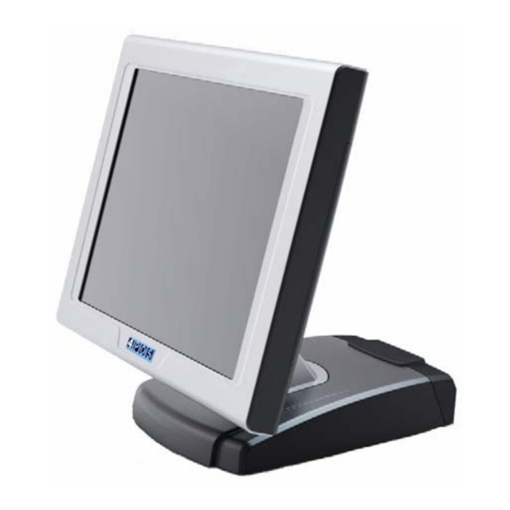
- Page 1 POS-400 Expander II All-in-One Point of Sales System User Manual Before installing and operating the unit, please read this user manual thoroughly and retain for reference. Ver 1.0_2009/12/30...
-
Page 2: How To Use This Manual
How to Use This Manual This manual contains information to set up and use the POS-400 Expander II. In addition, instructions are included for added hardware, upgrades, and optional items, as well as for software. Chapter 1 An introduction to what you find in the box and an overview of product specifications, appearance, and interface. - Page 3 Federal Communications Commission (FCC) Notice This equipment has been tested and found to comply with the limits for a Class A digital device, pursuant to Part 15 of the FCC Rules. These limits are designed to provide reasonable protection against harmful interference in a residential installation.
- Page 4 Copyright The information in this guide is subject to change without prior notice. The manufacturer shall not be liable for technical or editorial errors or omissions contained herein, nor for incidental or consequential damages resulting from the furnishing, performance, or use of this material. This manual contains information protected by copyright.
- Page 5 Precautions 1. Please read these safety instructions carefully. 2. Keep this User Manual for later reference. 3. Disconnect this equipment from the AC outlet before cleaning. Do not use liquid or spray detergent for cleaning. Use only a moistened sheet or cloth. 4.
-
Page 6: Table Of Contents
Contents Chapter 1 Introduction ....................1 Features ............................... 1 Specifications ............................1 Package Contents..........................3 Base System ............................4 Expandable Main Display ........................5 Convertible Pole-Type 2nd Display (optional) ..................6 Dimensions ............................7 Connector Panel ............................ 8 Chapter 2 Standard Hardware and Upgrades.............. - Page 7 Wireless LAN Driver Installation (optional) .................... 41 RFID Driver Installation (optional) ......................43 MSR Driver Installation (optional) ......................44 Fingerprint Reader Driver Installation (optional) ..................45 IC Card Reader Driver Installation (optional) ..................47 System Driver Installation (Required for Cash Drawer) ................48 OPOS CCO Driver Installation .......................
-
Page 8: Chapter 1 Introduction
5 x COM, 6 x USB, 1 x CF II • Flexible options: MSR, I-Button, Fingerprint, RFID, WiFi and Bluetooth • RoHS compliant Specifications POS-400 Expander II System Configuration CPU (μPGA) Intel® Atom Processor N270 1.6GHz fanless System Chipset Intel 945GSE+ICH7M... - Page 9 Audio Port 1 x Line-out, 1 x Mic-in Speaker 2 x internal stereo 2W speakers Mechanics and Environment Construction magnesium-aluminum alloy housing 268.5(D) x 380(W) x 350.3(H) mm Dimensions 296.6(D) x 380(W) x 350.3(H) mm (with pole I/O cover) Housing Color Silver/Black, Black Net Gross Weight 7.5 Kg (with VFD and MSR)
-
Page 10: Package Contents
Package Contents The following items come standard with the POS-4200 Expander 2: POS System Power Adaptor Utility and Main Board Chipset AC Power Cord Driver CD Options • Magnetic Stripe Reader (MSR) Module: triple track* • 2-in-1 Module (Magnetic Stripe Reader + Fingerprint Reader) * •... -
Page 11: Base System
Base System Before you begin, take a few moments to become familiar with the POS-420 Expander 2. 15inch Touch Screen I/O Cover Base Contrast Control Buttons Lighter Darker Hinge Arm left side Arm right side Power Button Left Speaker Right Speaker USB Port... -
Page 12: Expandable Main Display
Expandable Main Display The four sides of the main display are specially designed for expandable functions and connect with one of the available internal USB ports or PS/2 for operation. Optimized for simple installation, these interfaces do not require any voltage setting adjustments. •... -
Page 13: Convertible Pole-Type 2Nd Display (Optional)
Convertible Pole-Type 2nd Display (optional) The pole-type 2nd display is for use with the POS system to display purchase prices and change amounts to customers. It is also capable of displaying advertising messages and announcements. Two types of pole mount display choices are available: a 8.9 inch LCD monitor and a 9 cm high, 2 lines with 20 characters each VFD. -
Page 14: Dimensions
Dimensions (Unit: mm) -
Page 15: Connector Panel
Connector Panel The POS-400 Expander II's primary connector panel is located at the rear. To clearly see the connector panel you must remove the I/O cover. NOTE: POS-400 Expander II's COM6 port is not a complete RS-232C signals, can not be used as a general use COM port, please refer to Chapter 4 for COM6 pin assignment. -
Page 16: Standard Hardware And Upgrades
Chapter 2 Standard Hardware and Upgrades Precautions Before performing hardware changes, be sure to carefully read all of the applicable instructions, cautions, and warnings in this guide. WARNING! To reduce the risk of personal injury from electrical shock, hot surfaces, or fire: Disconnect the power cord from the wall outlet and allow the internal system components to cool before touching. -
Page 17: Opening Base Cover
Opening Base Cover CAUTION: To prevent loss of work and damage to the system or drive: If you are inserting or removing a drive, shut down the operating system properly, turn off the system, and unplug the power cord. Do not remove a drive while the system is on or in standby mode. -
Page 18: Clearing Cmos
Clearing CMOS The POS-400 Expander II's configuration (CMOS) may occasionally be corrupted. If it is, it will be necessary to clear the CMOS memory using jumper JP1. Please refer to Chapter 4 for the exact JP1 pin positions. 1. Turn off the system power properly through the operating system, then turn off any external devices. -
Page 19: Compact Flash Card Installation
Compact Flash Card Installation 1. Turn off the system power properly through the operating system, then turn off any external devices. 2. Disconnect the power cord from the power outlet and disconnect any external devices. CAUTION: Regardless of the power-on state, voltage is always present on the main board as long as the system is plugged into an active AC outlet. - Page 20 5. Replace the CF cover and replace the main unit to an upright position. 6. Reconnect the power cord and any external devices, then turn on the system. The system should automatically recognize the CF card when the system power is turned on. NOTE: CF card and 2.5 inch HDD master/slave setting: The system allows the use of both the CF card and hard disk at the same time,...
-
Page 21: Memory Installation
Memory Installation The memory sockets on the main board can be populated with an industry-standard DIMM. The POS-400 Expander II comes standard with one preinstalled DIMM. To achieve maximum memory performance, up to 2GB of memory can be changed. CAUTION: You must disconnect the power cord and wait approximately 30 seconds for the power to drain before adding or removing memory cards. - Page 22 CAUTION: To avoid scratching the panel, before doing dismantling, put a piece of cloth or cushion under the main unit. 4. If an existing memory card or cards need to be replaced, pull the ends of both metal latches away from the card to release it.
-
Page 23: Removing And Replacing The Sata Hard Disk
Removing and Replacing the SATA Hard Disk NOTE: This system does not support Parallel ATA (PATA) hard drives. Before removing the original hard drive, be sure to back up its data so that you can transfer the data to the replacement hard drive. Also, if you are replacing the primary hard drive, make sure you have a recovery disc set to restore the operating system, software drivers, and any software applications that were preinstalled on the system. - Page 24 6. Insert the replacement hard disk into the HDD box, and re-secure the screws. 7. Slide the HDD box back into the panel, ensuring that it is pressed all the way in and properly seated. 8. Reattach the two screws that secure the HDD box. 9.
-
Page 25: Chapter 3 Optional Components And Peripherals
Chapter 3 Optional Components and Peripherals MSR/Fingerprint/I-Button Module Installation NOTE: The MSR module can only be installed to its designated position and socket; the same with the wireless module. Their locations are not interchangeable. 1. Turn off the system power properly through the operating system, then turn off any external devices. - Page 26 NOTE: The MSR module configuration tool be put under <CD>\ Optional Module Data & Tool\MSR . If you need config MSR Module or test MSR module, please execute the utility under <CD>\ Optional Module Data & Tool\MSR...
-
Page 27: Wireless Module Installation
Wireless Module Installation 1. Turn off the system power properly through the operating system, then turn off any external devices. 2. Disconnect the power cord from the power outlet and disconnect any external devices. CAUTION: Regardless of the power-on state, voltage is always present on the main board as long as the system is plugged into an active AC outlet. -
Page 28: Rear Mount Vfd Installation (Need Usb Driver)
Rear Mount VFD Installation (need install rear mound USB driver) 1. Turn off the system power properly through the operating system, then turn off any external devices. 2. Disconnect the power cord from the power outlet and disconnect any external devices. CAUTION: Regardless of the power-on state, voltage is always present on the main board as long as the system is plugged into an active AC outlet. - Page 29 7. Reconnect the power cord and any external devices, then turn on the system. NOTE: The rear mound VFD module configuration utility be put under <CD>\ Optional Module Data & Tool\VFD\RearMount VFD . If you need it, please execute the utility under <CD>\ Optional Module Data &...
-
Page 30: Rfid Module Installation
RFID Module Installation 1. Turn off the system power properly through the operating system, then turn off any external devices. 2. Disconnect the power cord from the power outlet and disconnect any external devices. CAUTION: Regardless of the power-on state, voltage is always present on the main board as long as the system is plugged into an active AC outlet. -
Page 31: Cash Drawer Installation
Cash Drawer Installation NOTE: Before connecting a cash drawer to the system, please make sure the driver voltage and cable pin assignment of the cash drawer matches the definition of the system's cash drawer port. Please refer to the Cash Drawer Power Select Connector section. -
Page 32: Pole-Type 2Nd Display Module Installation
VGA port respectively. If you are installing pole type VFD, it has only a VFD cable to connect to POS-400 Expander II COM6 port. Then the plastic clip on the I/O cover must lock over the end of the base. -
Page 33: Chapter 4 Peb-973A Main Board Configuration
Chapter 4 PEB-973A Main Board Configuration Jumper and Connector Locations Connector Allocation Connector Function LPC port 80 daughter card connector SATA and IDE active LED SATA drive power connector Reserved LVDS back light inverter connector USB port 2 SATA port 0 Battery socket SATA port 2 Suspend LED connector... -
Page 34: Connectors Pin Assignments
PS/2 KB and MS connector Front panel connector COM6 connector Printer port USB port 1, USB port 4 and GIGA LAN RJ-45 connector Speaker out and MIC connector COM1, COM2 connector. Upper is COM1; Lower is COM2 RJ-11 connector +12V DC power input COM5 connector VGA connector CF card socket ( on the solder side ) - Page 35 Parallel Port LPT1 SCSI Connector PIN No. Description PIN No. Description STBX ACKX BUSY SLCT AFDX INITX SLINX VGA Port D-Sub15 Connector PIN No. Description PIN No. Description GREEN BLUE Reserved DDC DATA HSYNC VSYNC DDC CLK LAN Port RJ-45 and USB Port1/Port4 Connector PIN No.
-
Page 36: External Com6 Port: Connector Pin Definitions
PIN No. Description Stereo line out Microphone input Bottom External COM6 Port: Connector Pin Definitions A COM6 cable transfers signals from the PEB-973A main board to the external COM6 port. PIN No. Description +12V Jumper Settings To set jumper positions, place the jumper shunt over the pins designated in the table (SHORT) or remove (NC) it from the jumper pins and store for future use. - Page 37 PIN No. Function 1-2 Short 3.3V 2-3 Short PS/2 KB and Mouse Interface Enable Selection PIN No. Function 1-2 NC Disable 1-2 Short Enable COM1 RI Function Selection PIN No. Function Short +5V output Short RI function Short +12V output COM2 RI Function Selection PIN No.
-
Page 38: Chapter 5 Software Setup
Chapter 5 Software Setup This system comes with a variety of drivers for different operating systems. A software CD is included in the package contents. Driver Software List Driver Driver Setup Location Intel Chipset <CD>:\Driver\POS-400 II\Intel INF\XP Intel Graphics <CD>:\Drive\POS-400 II\VGA\Winxp ELO Touch Screen <CD>:\Driver\POS-400 II\Touch\ELO Abon Touch Screen... -
Page 39: Intel Chipset Driver Installation
Intel Chipset Driver Installation The chipset driver is needed to get the full potential from the POS-400 Expander II chipset. It should be loaded before other drivers and first thing after booting XP or Vista. 1. Run the infinst_autol.exe file on the CD in folder 2. -
Page 40: Intel Graphics Driver Installation
Intel Graphics Driver Installation 1. Locate and Run the winxp_14324.exe file on the CD in folder <CD>:\Driver\POS-400 II\ 2. Click Next on the Startup screen. VGA\winxp 3. Wait a moment for extract install driver software 4. Click Next on the Welcome screen. on your computer. - Page 41 7. Click Next on the Setup Progress screen. 8. Click Next on the Setup Progress screen. 9. When installation is complete, click Finish and restart the system.
-
Page 42: Elo Touch Screen Driver Installation
ELO Touch Screen Driver Installation 1. Locate and Run the sw600188.exe file on the CD 2. Click Unzip on the WinZip Self-Extractor window. in folder <CD>:\Driver\ POS-400 II\Touch\Elo 3. Select Default installation language then click 4. Select Install Serial Touchscreen Drivers and Next. - Page 43 7. Select COM3 then click Next. 8. Click Next. 10. After the computer has restarted, click the Align 9. When installation is complete, click Finish and button on the Elo Touchscreen Properties restart the system. screen. 11. Calibrate the three red points as instructed.
-
Page 44: Abon Touch Screen Driver Installation
Abon Touch Screen Driver Installation 1. Locate and Run the autorun.exe file on the CD 2. Select Setup Touch Package (for all Windows- in folder <CD>:\Driver\POS-400 II\Touch\Abon Vista32. 3. Click Next. 4. Click Next. 5. Select Install RS232 driver and click Next. 6. - Page 45 7. Click Finish. 8. Click Continue Anyway. 9. Click OK to reboot the system. 10. Run the Touch Tool on the desktop. 11. Select Advance, then click 4 Pts Calibration.
-
Page 46: Audio Driver Installation
Audio Driver Installation 1. Locate and Run the WDM_R209.exe file on the 2. Wait a moment for extract install driver software CD in folder<CD>:\Driver\POS-400 II \ on your computer. audio\WDM_R202 3. .Click Next on the Welcome screen. 4. Wait until the Audio driver have been installed. 5. -
Page 47: Ethernet Driver Installation
Ethernet Driver Installation 1. Locate and Run the setup.exe file on the CD in folder <CD>:\Driver\ POS-400 II\ 2. Click Next on the Welcome screen. LAN\PCIE_Install_5698_0822 4. Wait until the Ethernet PCI-E NIC driver has 3. Click Install on the Ready to install screen. been installed. -
Page 48: Wireless Lan Driver Installation (Optional)
Wireless LAN Driver Installation (optional) 1. First, plug in the USB WLAN Interface Module. 2. Locate and Run the setup.exe file on the CD in folder <CD>:\Driver\ Optional Module driver\ 3. Click Next on the License Agreement screen. WLAN\802.11bg 4. Select Ralink Configuration Tool then click Next. 5. - Page 49 8. When installation is complete, click Finish.
-
Page 50: Rfid Driver Installation (Optional)
RFID Driver Installation (optional) 1. Plug in the USB RFID Module and wait for the following screen. 3. Select Install from a list specific location then 2. Select Yes, this time only and then click Next. click Next. 5. Click Finish to complete the USB Serial Converter 4. -
Page 51: Msr Driver Installation (Optional)
MSR Driver Installation (optional) 1. First, plug-in the MSR module. 2. Reboot system to complete installation. -
Page 52: Fingerprint Reader Driver Installation (Optional)
Fingerprint Reader Driver Installation (optional) 1. Plug in the 2-in-1 Fingerprint Reader and MSR module. 2. Locate and Run the setup.exe file in folder <CD>:\Driver\Optional Module driver\ 3. Click Next on the Welcome screen. FingerPrint\URU4000B\DP Plat frsw 3.2 4. Click Next on the License Agreement screen. 5. - Page 53 8. Click Yes to restart the system (required).
-
Page 54: Ic Card Reader Driver Installation (Optional)
IC Card Reader Driver Installation (optional) 1. Plug in the 3-in-1 MSR, I-Button and IC Card Reader module. 2. Locate and Run the setup.exe file in folder <CD>:\Driver\Optional Module driver\ 3. Select language, then click OK. IC Card Reader\EZ100PU Driver 4. -
Page 55: System Driver Installation (Required For Cash Drawer)
System Driver Installation (Required for Cash Drawer) 1. Locate and Run the setup.exe file in folder <CD>:\Driver\POS-400 Expander II\ 2. Click Next on the Welcome screen. System Driver 4. Click Finish on the Completing installation screen. 3. Click Install on the Ready to Install screen. -
Page 56: Opos Cco Driver Installation
OPOS CCO Driver Installation Before installing the OPOS CCO driver, please make sure the system driver has been installed. 5. Locate and Run the OposCCOs-1_12_000.exe 6. Click Next on the Welcome screen. file in folder <CD>:\Driver\OPOS\CCOs 7. Click Next on the ReadMe screen. 8. - Page 57 11. Click Next on the Start Installation screen. 12. Wait system registering the control object 13. Click Finish on the Installation Complete screen.
-
Page 58: Opos Driver Installation
OPOS Driver Installation The OPOS driver for the POS-400 Expander II supports the Cash Drawer, MSR, I-Button (KeyLock), RFID, VFD (Line Display), UPS (Power). Before installing the OPOS driver, please make sure the system driver and OPOS CCO driver have been installed. -
Page 59: Appendix A. Sample C++ Cash Drawer Code For Windows
Appendix A. Sample C++ Cash Drawer Code for Windows NOTE: Requires installation of System Driver. Refer to the System Driver Installation section for instructions. 1. Open Cash Drawer // IOCTL Codes #define GPD_TYPE 56053 #define ADV_OPEN_CTL_CODE CTL_CODE(GPD_TYPE, 0x900, METHOD_BUFFERED, FILE_ANY_ACCESS) #define ADV_STATUS_CTL_CODE CTL_CODE(GPD_TYPE, 0x901, METHOD_BUFFERED, FILE_ANY_ACCESS) void OpenDrawer(UCHAR uWhichDrawer) // uWhichDrawer = 1 =>... - Page 60 &ulBytesReturned, NULL); if (bRet == FALSE || ulBytesReturned != 1) AfxMessageBox("Failed to Read from cash drawer driver"); CloseHandle(hFile); return; else AfxMessageBox(ReadByte ? “Drawer Open” : “Drawer Closed”); CloseHandle(hFile);...
-
Page 61: Appendix B. Sample Visual Basic Cash Drawer Code For Windows
Appendix B. Sample Visual Basic Cash Drawer Code for Windows NOTE: Requires installation of System Driver. Refer to the System Driver Installation section for instructions. ‘ Use inside a form’s code section and use Option Explicit Private Declare Function CreateFile Lib "kernel32" Alias "CreateFileA" _ (ByVal lpFileName As String, ByVal dwDesiredAccess As Integer, _ ByVal dwShareMode As Integer, ByVal lpSecurityAttributes As IntPtr, _ ByVal dwCreationDisposition As Integer, ByVal dwFlagsAndAttributes As Integer, _... - Page 62 ' Get Drawer Status iRet = DeviceIoControl(DeviceHandle, ADV_STATUS_CTL_CODE, 0, 0, iStatus, 4, iBytesRtn, 0) If (iRet = 0 Or iBytesRtn <> 1) Then Debug.Print("Error writing to Cash Drawer Driver. Error" & Err.LastDllError) End If If (iStatus = 0) Then StatusText.Text = "Cash Drawer(s) Closed" Else StatusText.Text = "Cash Drawer(s) Open"...
Need help?
Do you have a question about the POS-400 Expander II and is the answer not in the manual?
Questions and answers