Table of Contents
Advertisement
Quick Links
Advertisement
Table of Contents

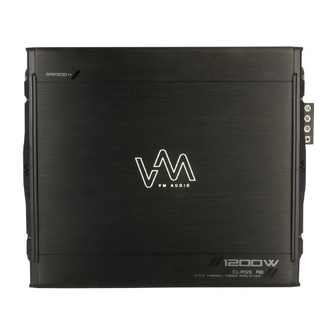
Summary of Contents for VM Audio SRA1200.4 Shaker Series
- Page 1 SRA1200.4 4 CHANNEL AMPLIFIER...
- Page 2 CONTENTS INTRODUCTION Thank you for your interest in VM Audio products. Our goal is to enhance your listening experience. INTRODUCTION The Shaker Series was designed as the economical solution for a performance craving, casual FEATURES consumer. The experts and engineers at VM Audio...
- Page 3 FUNCTIONS Front Panel Rear Panel 1. INPUT: Audio Cable Jack Connections 7. POWER INPUT: Power Cable Terminal 2. GAIN: Input Signal Adjustment Knob 8. FUSE: In-Line Protection Fuse(s) 3. BASS BOOST: Bass Adjustment Knob 9. SPEAKER OUTPUT: Speaker Wire Terminal 4.
-
Page 4: Getting Started
GETTING STARTED Mounting Wiring • Mount the amplifier on a flat, secure surface. • Before you begin routing and connecting the • Investigate the layout of your automobile power wires, disconnect the negative ground thoroughly before drilling. cable from the vehicle’s battery. •... -
Page 5: Power Connections
5. Route the power cable from the in-line fuse phillips screwdriver. to the amplifier’s power terminal (or a power capacitor such as VM Audio SRCAP2.0). 6. Connect the power cable to the in-line fuse WARNING! Be aware of gas tanks, gas lines, hydraulic and the other end to the amplifier’s positive +12V... - Page 6 POWER CONNECTIONS Continued... The remote wire, when connected to the amplifier, is For a good electrical connection and maximum power designed to turn on the amplifier automatically when transfer, use the same gauge size ground cable as your stereo is turned on. the power cable.
-
Page 7: Audio Input
AUDIO INPUT The audio inputs on the side panel of the amplifier If your car stereo head unit only has two line receive low level signals from the RCA outputs outputs (left and right), RCA “Y” adaptors will be of the stereo head unit. All of the amplifiers line needed to split the left and right signals into two inputs need to be connected to the stereo in order right channels and two left channels, one of each... -
Page 8: Speaker Wiring
SPEAKER WIRING Full Range Speaker Wiring Component Speaker Wiring 2Ω - 4Ω SPEAKER 2Ω - 4Ω IMPEDANCE SPEAKER IMPEDANCE Observing polarity, connect each speaker to each output channel of the amplifier terminal. Observing polarity, connect each speaker to each output channel of the amplifier terminal. Amplifier Crossover Settings Amplifier Crossover Settings 80 Hz... - Page 9 SPEAKER WIRING CONTROLS Continued... Subwooer Bridge Wiring Description Gain: This feature controls the audio input signal strength going into the amplifier. Bass Boost: Increases the bass level from +1dB up to +18dB. LPF: Low pass filter that reduces the signal level of frequencies above the bass region.
- Page 10 CALIBRATION Setting Gain Setting Bass Boost 1. Turn the gain and bass control all the way 1. Turn the gain and bass control all the way down (counterclockwise). down (counterclockwise). 2. Turn the vehicle, on and make sure the source 2.
-
Page 11: Troubleshooting
TROUBLESHOOTING AMPLIFIER FUSE KEEPS BLOWING? 1) Incorrect If the amplifier does not appear to be working, check for blown fuses, poor or incorrect wiring connections wiring or short circuit: Using your DMM, make sure and incorrect settings. that all voltage polarities are correct, Review section (Installation) for proper wire connection. -
Page 12: Specifications
SPECIFICATIONS Notes MODELS SRA1200.4 OUTPUT CHANNELS POWER per channel 4Ω 300W 2Ω 600W 4Ω Bridged 1200W THD-N @ 4Ω <0.05% FREQ. RESPONSE 20Hz - 25kHz LOWPASS 50 - 250Hz SUBSONIC BASS BOOST 0dB - 12dB INPUT SENSITIVITY 200mV - 8V INPUT IMPEDANCE 22k Ω... - Page 13 CONSUMER LIMITED WARRANTY AGREEMENT Your product is covered by a limited warranty by VM Audio as established below: Include a copy of the original receipt or invoice with the purchase date, dealer’s name, customer’s name and invoice Mobile Electronics Limited Warranty number clearly visible.


Need help?
Do you have a question about the SRA1200.4 Shaker Series and is the answer not in the manual?
Questions and answers