Table of Contents
Advertisement
Quick Links
Advertisement
Table of Contents

Related Manuals for Rockford Fosgate Power T15kW


Summary of Contents for Rockford Fosgate Power T15kW
-
Page 2: Table Of Contents
U.S. call 1-800-669-9899 or FAX 1-800-398-3985. For all other countries, call +001-480-967-3565 or FAX +001-480-967-8132. If, after reading your manual, you still have questions regarding this product, we recommend that you see your Rockford Fosgate dealer. If you need further assistance, you can call us direct at 1-800-669-9899. -
Page 3: Practice Safe Sound
We strongly suggest you have this amplifier installed by an Authorized Rockford Fosgate Dealer for your safety and ease of mind. This symbol with “WARNING” is intended to alert the user to the presence of important instructions. -
Page 4: Design Features
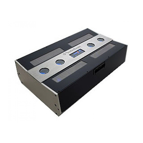
ESIGN EATURES Back Panel — RCA Inputs, Power Connection and Speaker Outputs Back Panel – RCA Inputs, Power Connection and Speaker Outputs 1. Power Terminals – The power and ground connectors on the amplifier are platinum-plated and will accommodate up to 1/0 AWG wire, maximizing the input current capability of the amplifier. - Page 5 ESIGN EATURES Top Panel — Status Boards 12. Available Power – These LEDs show the reserve energy of the hybrid system available for output power. NOTE: If the available power display constantly reads below 70%, check the supply power system or reduce the amount of load connected to the amplifier.
-
Page 6: Hybrid Technology
ESIGN EATURES Hybrid Technology By Anthony D'Amore - Rockford Design Engineer Some people have referred to Ohm's Law (circa 1827) and immediately say this amplifier is impossible. Ohm's Law has been correct for 179 years and I'm sure it will remain correct for many years to come.This technology is in no way breaking Ohm's Law. The real law that we need to talk about is the 1st law of thermal dynamics or Conservation of Energy.This law states that energy cannot be created nor destroyed;... -
Page 7: Installation
Due to the weight and size of this amplifier, and for your safety and ease of mind, we strongly suggest you have this amplifier installed by an Authorized Rockford Fosgate Dealer. The following is a list of tools needed for installation:... -
Page 8: Battery And Charging
NSTALLATION BATTERY AND CHARGING This amplifier will draw a maximum of 350 - 375 Amps of current. Therefore for 'street' it is recommended to use a minimum of 2 additional batteries, as well as a high output alternator. These requirements do not change for competition use, as the amplifier will deliver the same amount of burst output power as long as the battery voltage is maintained between 11.0V and 15.5V. - Page 9 NSTALLATION 9. Connect the speakers. Strip the speaker wires 5/8" and insert into the speaker terminal and tighten the binding nut to secure into place. Be sure to maintain proper speaker polarity. DO NOT chassis ground any of the speaker leads as unstable operation may result. Use the following chart for the recommended wire SPEAKER WIRE SIZE CHART size for the load connected.
-
Page 10: Example System Configurations
NSTALLATION Example System Configurations Example 1 Here are some examples of 'street' setups utilizing the Selectable Power Output operation. Example 1: Two sets of 4-ohm component speakers in series on channels 1 and 2. One dual voice coil 4-ohm subwoofer with coils in series to channels 3 and 4 bridged. - Page 11 NSTALLATION Example 3: Four sets of component speakers in parallel on channels 1 and 2. Six dual 4-ohm voice coil subwoofers in series-parallel combination to channels 3 and 4 bridged. This provides the amplifier with 1-ohm stereo loads on channels 1 and 2 and a 1.5-ohm bridged load on channels 3 and 4.
- Page 12 NSTALLATION Example 4: So, those other examples just wasn’t enough for you. You want something for the ultimate tailgate party or maybe BLOCK PARTY. Here’s a system for you! Twelve (12) sets of component speakers in series-parallel on channels 1 and 2. Sixteen (16) dual 2-ohm voice coil subwoofers in series-parallel combination to channels 3 and 4 bridged.
-
Page 13: Operation
PERATION ADJUSTING GAIN (Rotary Knob) 1. Disconnect the speakers from the amplifier. 2. Switch both crossovers to AP (All Pass - Center position). 3. Turn both gain controls to 0dB (counter-clockwise all the way). 4. Insert a disc containing a -10dB 1kHz test tone into the source unit. Play the test tone and set source to repeat if necessary. 5. -
Page 14: Troubleshooting
ROUBLESHOOTING When troubleshooting, sometimes it’s the simplest things we overlook. Like loose connections, blown fuses or maybe the source unit was switched to mute. Before getting too in depth, check the simple things first. Amplifier does not come on. 1. Verify power connections at amplifier. Check battery connections. 2. -
Page 15: Specifications
PECIFICATIONS Continuous Power Rating (RMS) - Measured at 14.4 Battery Volts Stereo Output Power 4 ohms 500 Watts RMS X 4 2 ohms 1000 Watts RMS X 4 1 ohm 2000 Watts RMS X 4 0.5 ohm 3750 Watts RMS X 4 Bridged Output Power 4 ohms 2000 Watts RMS X 2... -
Page 16: Limited Warranty Information
Some states do not allow limitations on the length of an implied warranty, so this limitation may not apply. No person is authorized to assume for Rockford Fosgate any other liability in connection with the sale of the product.