Payne PG8J Installation Instructions Manual
Single-stage deluxe induced-combustion 4-way multipoise furnace
Hide thumbs
Also See for PG8J:
Table of Contents
Advertisement
PG8J
PG8M
. . . . . . . . . . . . . . . . . . . . . . . . . . . . . . . . . .
. . . . . . . . . . . . . . . . . . . . . . . . . . . . . . . . . .
. . . . . . . . . . . . . . . . . . . . . . . . . . . .
. . . . . . . . . . . . . . . . . . . . . . . . . . . . . . . .
. . . . . . . . . . . . . . . . . . . . . . . . . . . . . . . . . . . . . . .
. . . . . . . . . . . . . . . . . . . . . . . . . . . . . . . . . . . . . . . .
. . . . . . . . . . . . . . . . . . . . . . . . . . . . . . . . . .
. . . . . . . . . . . . . . . . . . . . . . . . . .
. . . . . . . . . . . . . . . . . . . . . . . . . . . . .
. . . . . . . . . . . . . . . . . . . . . . . . . .
. . . . . . . . . . . . . . . . . . . . . . . . . . . . .
. . . . . . . . . . . . . . . . . . . . . . . . . .
. . . . . . . . . . . . . . . . . . . . . . . . . . . . .
. . . . . . . . . . . . . . . . . . . . . . . . . . . .
. . . . . . . . . . . . . . . . . . . . . . . . . .
. . . . . . . . . . . . . . . . . . . . . . . . . .
. . . . . . . . . . . . . . . . . . . . . . . . . . . . . . . . . .
. . . . . . . . . . . . . . . . . . . . . . . . . . . . . . .
. . . . . . . . . . . . . . . . . . . . . . . . . . . . . . . . . . .
. . . . . . . . . . . . . . . . . . . . . . . . . . . . . . . . . . . .
Installation Instructions
. . . . . . . . . . . . . . . . . . . . . . . .
. . . . . . . . . . . . . . . . . . . . . . . . . .
. . . . . . . . . . . . . . . . . . . . . . .
. . . . . . . . . . . . . .
. . . . . .
. . . . . .
. . . . . . . . . . . . . . . . . . . . .
. . . . . . . . . . . . . .
. . . . . . . . .
. . . . . . . . . . . . . . . . . . . .
. . . . . . . . . . . . . . . . . . . . . . . .
. . . . . . . . . . . . . . . . . . . . . . .
. . . . . . . . . . . . . . . . . . . . . . . . .
. . . . . . . . . . . . . . . . . . . .
. . . . . . . . . . . . . . . . . . . . .
. . . . . . . . . . . . . . . . .
. . . . . . . . . . . . . . . . . . . . . .
. . . . . . . . . . . . . . . . . . . . .
4---WAY MULTIPOISE FURNACE
2
3
4
4
4
4
5
5
5
5
5
6
6
7
7
8
11
11
11
11
12
12
13
13
13
13
13
13
13
NOTE: Read the entire instruction manual before starting the
20
installation.
22
Portions of the text and tables are reprinted from NFPA 54/ANSI
22
Z223.1- -2006E, with permission of Nation Fire Protection
Association, Quincy, MA 02269 and American Gas Association,
22
Washington DC 20001. This reprinted material is not the
23
complete and official position of the NFPA or ANSI on the
23
referenced subject, which is represented only by the standard in
its entirely.
25
25
25
1
SINGLE---STAGE DELUXE
INDUCED---COMBUSTION
. . . . . . . . . . . . . . . . . . .
. . . . . . . . . . . . . . . .
. . . . . . . . . . . . . . . . . . .
. . . . . . . . . . . . . . . . . . . . . . . . . . . . . . . .
. . . . . . . . . . . . . . . . . . . . . . . . . . . . . . .
. . . . . . . . . . . . . . . . . . . . .
. . . . . . . . . . . . . . . . . . . . . . . . . . . .
. . . . . . . . . . . . . . . . . . . .
. . . . . . . . . . . . . . . . . . . . . . . . . . . . . .
. . . . . . . . . . . . . . . . . . . . . . . . . . . .
. . . . . . . . . . . . . . . . . . . .
. . . . . . . . . . . . . . . . . . . .
. . . . . . . . . . . . . . . . . . . . . . . .
. . . . . . . . . . . . . . . . . . . . . . . . .
ama
ISO 9001:2000
CERTIFIED
REGISTERED
26
28
29
30
. . . . .
31
31
31
34
37
38
. . . . . . .
45
45
47
49
50
50
Advertisement
Table of Contents

Subscribe to Our Youtube Channel
Related Manuals for Payne PG8J


Summary of Contents for Payne PG8J
-
Page 1: Table Of Contents
SINGLE---STAGE DELUXE PG8J PG8M INDUCED---COMBUSTION 4---WAY MULTIPOISE FURNACE Installation Instructions SAFETY CONSIDERATIONS ......Masonry Chimney Requirements .... -
Page 2: Safety Considerations
SAFETY CONSIDERATIONS WARNING Improper installation, adjustment, alteration, service, maintenance, or use can cause explosion, fire, electrical shock, or FIRE, EXPLOSION, ELECTRICAL SHOCK, AND other conditions which may cause death, personal injury, or CARBON MONOXIDE POISONING HAZARD property damage. Consult a qualified installer, service agency, or Failure to follow this warning could result in personal injury, your distributor or branch for information or assistance. -
Page 3: Introduction
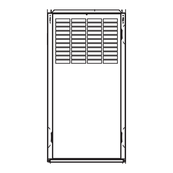
28-7/8" 26-1/8" (FLUE COLLAR) 25-1/4" 2-7/16" 22-9/16" AIRFLOW 1-5/16" 19" 13/16" JUNCTION BOX 13/16" 1-1/8" LOCATION OUTLET 4-13/16" 5-15/16" 1/2" DIA. K.O.THERMOSTAT WIRE ENTRY 9-5/8" 11/16" 8-9/16" 7/8" DIA 1-3/4" DIA.RIGHT HAND 7-3/4" ACCESSORY GAS ENTRY 1/2" DIA THERMOSTAT 11-1/2" WIRE ENTRY 3-15/16"... -
Page 4: Codes And Standards
INSTALLATION MINIMUM INCHES CLEARANCE TO COMBUSTIBLE CONSTRUCTION DISTANCE MINIMALE EN POUCES AUX CONSTRUCTIONS COMBUSTIBLES This forced air furnace is equipped for use with This furnace is approved for UPFLOW, DOWNFLOW, and HORIZONTAL installations. natural gas at altitudes 0-10,000 ft (0-3,050m). accessory kit, supplied... -
Page 5: Step 4 -Duct Systems
ELECTROSTATIC DISCHARGE (ESD) CANADA: Part 7 of NSCNGPIC, Venting Systems and Air Supply for Appliances PRECAUTIONS PROCEDURE Step 4 —Duct Systems CAUTION US and CANADA: Air Conditioning Contractors As- sociation (ACCA) Manual D, Sheet Metal and Air Conditioning Contractors National Association FURNACE RELIABILITY HAZARD (SMACNA), or American Society of Heating, Refriger- Failure to follow this caution may result in furnace... -
Page 6: Location
TABLE 1—DIMENSIONS (IN.) FURNACE SIZE FLUE SHIP WT (LB) CABINET WIDTH SUPPLY ---AIR RETURN---AIR C.L. TOP AND COLLAR* WIDTH (IN.) WIDTH (IN.) BOTTOM FLUE (IN.) COLLAR (IN.) 045---08/024045 14--- 3/16 12--- 9/16 12--- 11/16 9--- 5/16 045---12/036045 14--- 3/16 12--- 9/16 12--- 11/16 9--- 5/16 070---08/024070... -
Page 7: Location Relative To Cooling Equipment
WARNING FIRE AND EXPLOSION HAZARD Failure to follow this warning could result in personal injury, death, and/or property damage. or explosion. When the furnace is installed in a residential garage, the burners and ignition sources must be located at least 18 inches above the floor. -
Page 8: Outdoor Combustion Air Method
AIR FOR COMBUSTION AND d. TWO OPENINGS OR VERTICAL DUCTS require 1 sq./in. of free area per 4,000 Btuh (550 mm2/kW) for VENTILATION combined input of all gas appliances in the space per Provisions for adequate combustion, ventilation, and dilution air Fig. - Page 9 TABLE 2—MINIMUM FREE AREA REQUIRED FOR EACH COMBUSTION AIR OPENING OR DUCT TO OUTDOORS TWO HORIZONTAL DUCTS SINGLE DUCT OR OPENING TWO OPENINGS OR VERTICAL DUCTS (1 SQ. IN./2,000 BTUH) (1,100 SQ. MM/KW) (1 SQ. IN./3,000 BTUH) (734 SQ. MM/KW) (1 SQ.
- Page 10 1 SQ IN. PER 4000 DUCTS BTUH* CIRCULATING AIR VENT THROUGH ROOF OUTDOORS DUCTS 12″ MAX 12″ 1 SQ IN. VENT 12" MAX PER 2000 THROUGH BTUH* ROOF 1 SQ IN. 1 SQ IN. PER 1000 4000 BTUH* IN DOOR BTUH* OR WALL DUCTS...
-
Page 11: Installation
Unusually tight construction is defined as Construction with: In upflow position with side return inlet(s), leveling legs may be used. (See Fig. 10.) Install field- -supplied, 5/16 X 1- -1/2 in. (max) a. Walls and ceilings exposed to the outdoors have a con- corrosion- -resistant machine bolts, washers and nuts. -
Page 12: Bottom Return Air Inlet
FURNACE CD5 OR CK5 COIL ASSEMBLY OR KCAKC COIL BOX COMBUSTIBLE PLENUM FLOORING OPENING FLOOR SHEET METAL OPENING PLENUM FLOOR OPENING A04140 A96283 A04140 Fig. 11 --- Floor and Plenum Opening Dimensions Fig. 13 --- Furnace, Plenum, and Coil Assembly or Coil Box Installed on a Combustible Floor NOTE: It is recommended that the perforated supply- -air duct Bottom Return Air Inlet... -
Page 13: Platform Furnace Support
If the screws are attached to ONLY the furnace sides and not the AIR DUCTS bottom, the straps must be vertical against the furnace sides and General Requirements not pull away from the furnace sides, so that the strap attachment The duct system should be designed and sized according to screws are not in tension (are loaded in shear) for reliable support. - Page 14 TABLE 4—OPENING DIMENSIONS (IN.) FURNACE PLENUM OPENING FLOOR OPENING CASING APPLICATION WIDTH Upflow Applications on Combustible or Noncombustible Floor- 12--- 11/16 21--- 5/8 13--- 5/16 22--- 1/4 ing (KGASB subbase not required) Downflow Applications on Noncombustible Flooring (KGASB 12--- 9/16 13--- 3/16 19--- 5/8 subbase not required)
- Page 15 TABLE 5—AIR DELIVERY - - CFM (WITH FILTER)* FUR- EXTERNAL STATIC PRESSURE (IN. WC) RETURN---AIR NACE SPEED INLET SIZE High 1085 1035 Bottom or 024045 Med --- High --- --- Side(s) Med --- Low --- --- High 1440 1375 1305 1240 1160 1070...
- Page 16 TABLE 5⎯ AIR DELIVERY - - CFM (WITH FILTER)* (CONTINUED) EXTERNAL STATIC PRESSURE (IN. WC) FURNACE RETURN---AIR SPEED SIZE INLET High 2090 2010 1930 1835 1710 1590 1470 1335 1025 Bottom or 048135 Med --- High 1790 1755 1705 1640 1550 1465 1360...
- Page 17 " THREADED ROD 4 REQ. OUTER DOOR ASSEMBLY SECURE ANGLE IRON TO BOTTOM OF FURNACE WITH 3 #8 x " SCREWS TYPICAL FOR 2 SUPPORTS 8" MIN FOR DOOR REMOVAL 1" SQUARE, 1 " x 1 " x " ANGLE IRON OR UNI-STRUT MAY BE USED (2) HEX NUTS, (2) WASHERS &...
- Page 18 LINE CONTACT ONLY PERMISSIBLE BETWEEN LINES FORMED BY INTERSECTIONS OF THE TOP AND TWO SIDES OF THE FURNACE JACKET AND BUILDING JOISTS, STUDS, OR FRAMING. ″ OVER ALL ″ UNDER DOOR 1″ UNDER FURNACE TYPE-B EXTEND OUT 12″ OUT ENTRY VENT FROM FACE OF DOOR I N *...
- Page 19 A02163 Fig. 19 --- Downflow Return Air Configurations and Restrictions A02162 Fig. 20 --- Horizontal Return Air Configurations and Restrictions Upflow and Horizontal Furnaces Downflow Furnaces Connect supply- -air duct to flanges on furnace supply- -air outlet. Connect supply- -air duct to supply- -air outlet on furnace. Bend Bend flange upward to 90_ with wide duct pliers.
-
Page 20: Return Air Connections
Refer to Table 6 for recommended gas pipe sizing. Risers must be WARNING used to connect to furnace and to meter. Support all gas piping with appropriate straps, hangers, etc. Use a minimum of 1 hanger every 6 ft. Joint compound (pipe dope) should be applied FIRE HAZARD sparingly and only to male threads of joints. - Page 21 national plumbing and gas codes before the furnace has been connected. After all connections have been made, purge lines and check for leakage at furnace prior to operating furnace. If pressure exceeds 0.5 psig (14- -in. wc), gas supply pipe must be disconnected from furnace and capped before and during supply pipe pressure test.
-
Page 22: 115- -V Wiring
NOTE: On 14 in. wide casing models, the J- -Box shall not be WARNING relocated to other side of furnace casing when the vent pipe is routed within the casing. ELECTRICAL SHOCK AND FIRE HAZARD 1. Remove and save two screws holding J- -Box. (See Fig. 23.) Failure to follow this warning could result in personal injury, death, or property damage. -
Page 23: Power Cord Install. Furnace J- -Box
TABLE 7—ELECTRICAL DATA MAXIMUM MAXIMUM OPERATING VOLTAGE VOLTS--- MAXIMUM MINIMUM FURNACE UNIT WIRE FUSE OR RANGE HERTZ--- UNIT WIRE SIZE AMPACITY# LENGTH CKT BKR PHASE AMPS GAUGE (FT.)‡ AMPS† Maximum Minimum* 045--- 08/024045 115--- 60--- 1 7.54 045--- 12/036045 115--- 60--- 1 9.50 070--- 08/024070 115--- 60--- 1... - Page 24 TWINNING AND/OR COMPONENT TEST BLOWER OFF-DELAY TERMINAL J2 JUMPER BLOWER OFF-DELAY HUMIDIFIER TERMINAL (24-VAC 0.5 AMP MAX.) 24-V THERMOSTAT TERMINALS TRANSFORMER 24-VAC CONNECTIONS TEST/TWIN 0.5 AMP@24VAC 3-AMP FUSE FUSE 3-AMP SEC-2 SEC-1 LED OPERATION & EAC-2 DIAGNOSTIC LIGHT PL1-LOW VOLTAGE MAIN HARNESS CONNECTOR 115-VAC(L2)NEUTRAL CONNECTIONS...
-
Page 25: 24- -V Wiring
24- -V WIRING WARNING Make field 24- -v connections at the 24- -v terminal strip. (See Fig. 25.) Connect terminal Y as shown in Fig. 26 for proper cooling CARBON MONOXIDE POISONING HAZARD operation. Use only AWG No. 18, color- -coded, copper thermostat wire. -
Page 26: Masonry Chimney Requirements
2. Do not connect this Category I furnace into a single- -wall 1. Vent connector is Type- -B double- -wall, and dedicated or common vent. The dedicated or common 2. This furnace is common vented with at least 1 draft hood vent is considered to be the vertical portion of the vent equipped appliance, and system that terminates outdoors. - Page 27 CHIMNEY INSPECTION CHART For additional requirements refer to the National Fuel Gas Code NFPA 54/ANSI Z223.1 and ANSI/NFPA 211 Chimneys, Fireplaces, Vents, and Solid Fuel Burning Appliances in the U.S.A. or to the Canadian installation Code CSA-B149.1 in Canada. Crown Rebuild condition: crown.
-
Page 28: Appliance Application Requirements
APPLIANCE APPLICATION REQUIREMENTS TABLE B–MINIMUM ALLOWABLE INPUT RATING OF SPACE- -HEATING APPLIANCE IN THOUSANDS OF Appliance operation has a significant impact on the performance BUT PER HOUR of the venting system. If the appliances are sized, installed, adjusted, and operated properly, the venting system and/or the INTERNAL AREA OF CHIMNEY appliances should not suffer from condensation and corrosion. -
Page 29: Additional Venting Requirements
A04127 Fig. 28 --- Using Tin Snips to Cut Tie Points Air for combustion must not be contaminated by halogen NOTE: An accessory flue extension KGAFE0112UPH is compounds which include chlorides, fluorides, bromides, and available to extend from the furnace elbow to outside the furnace iodides. -
Page 30: Sidewall Venting
A04129 Fig. 30 --- Knockout Pulled Loose A04128 Fig. 29 --- Rounded End of Knockout For the knockouts in the other locations on the door (top and sides), tin snips can also be used along the door edges; however, the preferred method is to use a hammer and screwdriver to strike a sharp blow (See Fig. -
Page 31: Start- -Up, Adjustment, And Safety Check
START- - UP, ADJUSTMENT, AND SAFETY CHECK Step 1 —General WARNING WARNING FIRE HAZARD ELECTRICAL SHOCK HAZARD Failure to follow this warning could result in personal Failure to follow this warning could result in personal injury, death and/or property damage. injury, or death. - Page 32 SEE NOTES: 1,2,4,7,8,9 SEE NOTES: 1,2,4,5,7,8,9 on the page following on the page following these figures these figures A03208 A03211 Fig. 33 --- Upflow Application- -Vent Elbow Up Fig. 36 --- Downflow Application- -Vent Elbow Up SEE NOTES: 1,2,4,5,6,7,8,9,10 SEE NOTES: 1,2,3,4,7,8,9 on the page following these figures on the pages following these figures...
- Page 33 SEE NOTES: 1,2,4,7,8,9 on the page following these figures SEE NOTES: 1,2,4,7,8,9 on the page following these figures A03213 A03218 Fig. 39 --- Horizontal Left Application- -Vent Elbow Left Fig. 43 --- Horizontal Right Application- -Vent Elbow Right SEE NOTES: 1,2,4,5,7,8,9 on the page following these figures SEE NOTES: 1,2,4,5,7,8,9 on the page following these figures...
-
Page 34: Step 3 -Adjustments
CAUTION!! FOR THE FOLLOWING APPLICATIONS, USE THE MINIMUM VERTICAL VENT HEIGHTS AS SPECIFIED BELOW. FOR ALL OTHER APPLICATIONS, FOLLOW EXCLUSIVELY THE NATIONAL FUEL GAS CODE. FURNACE VENT FURNACE MINIMUM VENT MINIMUM VERTICAL VENT ORIENTATION ORIENTATION INPUT(BTUH/HR) DIAMETER (IN.)* HEIGHT (FT.)** Vent elbow left, then 154,000 132,000 Downflow... - Page 35 g. Replace orifice with correct size if required by Table see radiant heat from heat exchangers. Radiant heat 12 or 13. Use only factory- -supplied orifices. See affects temperature rise readings. This practice is par- EXAMPLE 2. ticularly important with straight- -run ducts. EXAMPLE 2: (0- -2000 ft.
- Page 36 A08411 Fig. 46 --- Wiring Diagram...
-
Page 37: Step 4 -Check Safety Controls
THERMOSTAT SUBBASE TERMINALS WITH THERMOSTAT REMOVED (ANITICIPATOR, CLOCK, ETC., MUST BE OUT OF CIRCUIT.) HOOK-AROUND AMMETER R Y W G 10 TURNS FROM UNIT 24-V CONTROL TERMINALS = 0.5 AMPS FOR THERMOSTAT EXAMPLE: 5.0 AMPS ON AMMETER ANTICIPATOR SETTING 10 TURNS AROUND JAWS A96316 A06666 Fig. -
Page 38: Step 5 -Checklist
TABLE 10—GAS RATE (CU FT./HR) SIZE OF TEST DIAL SIZE OF TEST DIAL SECONDS FOR 1 SECONDS FOR 1 1 Cu Ft 2 Cu Ft 5 Cu Ft 1 Cu Ft 2 Cu Ft 5 Cu Ft REVOLUTION REVOLUTION 1800 1636 1500 1385... - Page 39 TABLE 12—ORIFICE SIZE* AND MANIFOLD PRESSURE FOR GAS INPUT RATE (TABULATED DATA BASED ON 22,000 BTUH PER BURNER, DERATED 4 PERCENT FOR EACH 1000 FT. ABOVE SEA LEVEL) SPECIFIC GRAVITY OF NATURAL GAS AVG.. GAS ALTITUDE RANGE HEAT VALUE 0.58 0.60 0.62 0.64...
- Page 40 TABLE 12–ORIFICE SIZE* AND MANIFOLD PRESSURE FOR GAS INPUT RATE (CONTINUED) (TABULATED DATA BASED ON 22,000 BTUH PER BURNER, DERATED 4 PERCENT FOR EACH 1000 FT. ABOVE SEA LEVEL) SPECIFIC GRAVITY OF NATURAL GAS AVG. GAS 0.58 0.60 0.62 0.64 ALTITUDE HEAT VALUE RANGE (FT.)
- Page 41 TABLE 12–ORIFICE SIZE* AND MANIFOLD PRESSURE FOR GAS INPUT RATE (CONTINUED) (TABULATED DATA BASED ON 22,000 BTUH PER BURNER, DERATED 4 PERCENT FOR EACH 1000 FT. ABOVE SEA LEVEL) SPECIFIC GRAVITY OF NATURAL GAS AVG. GAS 0.58 0.60 0.62 0.64 HEAT VALUE ALTITUDE RANGE AT ALTITUDE...
- Page 42 TABLE 13—ORIFICE SIZE* AND MANIFOLD PRESSURE FOR GAS INPUT RATE (TABULATED DATA BASED ON 21,000 BTUH PER BURNER, DERATED 4 PERCENT FOR EACH 1000 FT. ABOVE SEA LEVEL) SPECIFIC GRAVITY OF NATURAL GAS 0.58 0.60 0.62 0.64 AVG. GAS ALTITUDE RANGE (FT.) HEAT VALUE Orifice Manifold...
- Page 43 TABLE 13—ORIFICE SIZE* AND MANIFOLD PRESSURE FOR GAS INPUT RATE (CONTINUED) (TABULATED DATA BASED ON 21,000 BTUH PER BURNER, DERATED 4 PERCENT FOR EACH 1000 FT. ABOVE SEA LEVEL) SPECIFIC GRAVITY OF NATURAL GAS AVG. GAS HEAT ALTITUDE 0.58 0.60 0.62 0.64 VALUE AT ALTI-...
-
Page 44: Component Test
TABLE 13—ORIFICE SIZE* AND MANIFOLD PRESSURE FOR GAS INPUT RATE (CONTINUED) (TABULATED DATA BASED ON 21,000 BTUH PER BURNER, DERATED 4 PERCENT FOR EACH 1000 FT. ABOVE SEA LEVEL) SPECIFIC GRAVITY OF NATURAL GAS AVG. GAS ALTITUDE RANGE 0.58 0.60 0.62 0.64 HEAT VALUE... -
Page 45: Service And Maintenance Procedures
SERVICE AND MAINTENANCE wiring during installation, service, or maintenance will cause this fuse to blow. If fuse replacement is required, use ONLY a 3- -amp. PROCEDURES fuse. The control LED will display status code 24 when fuse needs to be replaced. WARNING Proper instrumentation is required to service electrical controls. - Page 46 Media cabinet filter procedures: For continuing high performance and to minimize possible equipment failure, periodic maintenance must be performed on NOTE: Media cabinet or 1 in. filter rack are accessories and are this equipment. Consult your local dealer about proper frequency not included from the factory with standard furnace model.
-
Page 47: Step 2 -Care And Maintenance
9. Clean blower wheel and motor using a vacuum with soft WARNING brush attachment. Blower wheel blades may be cleaned with a small paint or flux brush. Do not remove or disturb balance weights (clips) on blower wheel blades. ELECTRICAL SHOCK HAZARD 10. - Page 48 striking with ball- -peen hammer. TIGHTNESS IS 9/32˝ VERY IMPORTANT. NOTE: The materials needed in item 9 can usually be purchased 5/16˝ at local hardware stores. (1.) Attach variable- -speed, reversible drill to the end of spring cable (end opposite brush). (2.) Insert brush end of cable into the outlet opening of cell and slowly rotate with drill.
-
Page 49: Step 3 -Sequence Of Operation
If flame is proved when flame should not be present, WARNING the furnace control CPU will lock out of Gas- -Heating mode and operate the inducer motor IDM until flame is no longer proved. FIRE OR EXPLOSION HAZARD e. Blower- -On Delay- - If the burner flame is proven, the Failure to follow this warning could result in personal blower motor is energized on HEAT speed 25 sec after injury, death and/or property damage. -
Page 50: Step 4 -Wiring Diagrams
continue running the blower motor at HEAT speed after the selected blower- -OFF delay period is completed. Step 4 —Wiring Diagrams Refer to Fig. 24 and 45 for wiring diagrams. Step 5 —Troubleshooting Refer to the service label. (See Fig. 50–Service Label.) The Troubleshooting Guide can be a useful tool in isolating furnace operation problems. - Page 52 Edition Date: 07/08 Catalog No: IM- - PG8J- - 10 Copyright 2008 Payne Heating & Cooling S 7310 W. Morris St. S Indianapolis, IN 46206 Replaces: IM- -PG8J- -09 Manufacturer reserves the right to change, at any time, specifications and designs without notice and without obligations.
Need help?
Do you have a question about the PG8J and is the answer not in the manual?
Questions and answers