Payne C Series Installation, Start-Up, Operating, Service And Maintenance Instructions
Hide thumbs
Also See for C Series:
Table of Contents
Advertisement
Quick Links
CLICK ANYWHERE on THIS PAGE to RETURN to PAYNE HVAC MANUALS & GUIDES at InspectApedia.com
Service and Maintenance Instructions
Catalog No: 53PG-8J5
Installation, Start-up, Operating, and
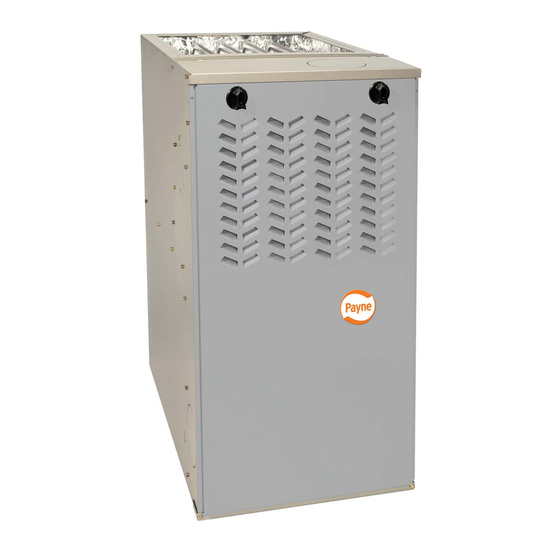
The Payne PG8M/PG8J 80% AFUE Gas Furnaces feature 4-
way multipoise design and through-the-furnace downflow
venting. The PG8M/PG8J furnaces are approved for use with
natural or propane gas and the PG8J is also approved for use in
Low Nox Air Quality Management Districts.
STANDARD FEATURES
•
•
•
•
LIMITED WARRANTY
• 20-year warranty on "Super S™" heat exchanger
• 5-year parts warranty on all other components
-Series C
Four-position furnace: upflow, horizontal right, horizontal
left, downflow
Electronic control center
Adjustable heating air temperature rise
LED diagnostics and self test feature
Hot surface ignition (HSI)
Twinning in Upflow, Downflow and Horizontal
Form No. IM-PG8J-05
PG8M/PG8J
5-05
Advertisement
Table of Contents

Related Manuals for Payne C Series


Summary of Contents for Payne C Series
- Page 1 CLICK ANYWHERE on THIS PAGE to RETURN to PAYNE HVAC MANUALS & GUIDES at InspectApedia.com PG8M/PG8J Installation, Start-up, Operating, and Service and Maintenance Instructions -Series C The Payne PG8M/PG8J 80% AFUE Gas Furnaces feature 4- way multipoise design and through-the-furnace downflow venting.
-
Page 2: Table Of Contents
Single-Stage Induced-Combustion 4-Way Multipoise Furnace Cancels: II 310A-45-4/IM-PG8J-04 II310A-45-5/IM-PG8J-05 Installation, Start-up, Operating, and Service and Maintenance Instructions Series 120/C NOTE: Read the entire instruction manual before starting the installation. This symbol → indicates a change since the last issue. → Portions of the text and tables are reprinted from NFPA 54/ANSI Z223.1-2002©, with permission of National Fire Protection Association, Quincy, MA 02269 and American Gas Association, Washington DC 20001. -
Page 3: Safety Considerations
28-7/8" 26-1/8" (FLUE COLLAR) 25-1/4" 2-7/16" 22-9/16" AIRFLOW 1-5/16" 19" 13/16" JUNCTION BOX 13/16" 1-1/8" LOCATION OUTLET 4-13/16" 5-15/16" 1/2" DIA. K.O.THERMOSTAT 9-5/8" WIRE ENTRY 11/16" 7/8" DIA 8-9/16" 1-3/4" DIA.RIGHT HAND 7-3/4" ACCESSORY GAS ENTRY 1/2" DIA THERMOSTAT 11-1/2" WIRE ENTRY 3-15/16"... - Page 4 INSTALLATION MINIMUM INCHES CLEARANCE TO COMBUSTIBLE CONSTRUCTION DISTANCE MINIMALE EN POUCES AUX CONSTRUCTIONS COMBUSTIBLES This forced air furnace is equipped for use with This furnace is approved for UPFLOW, DOWNFLOW, and HORIZONTAL installations. natural gas at altitudes 0-10,000 ft (0-3,050m). accessory kit, supplied...
-
Page 5: Introduction
→ Table 1—Dimensions (IN.) C.L. TOP AND FLUE FURNACE SUPPLY-AIR RETURN-AIR BOTTOM COLLAR* SHIP WT. (LB) SIZE CABINET WIDTH WIDTH WIDTH FLUE COLLAR (IN.) (IN.) (IN.) (IN.) 045-08/024045 14-3/16 12-9/16 12-11/16 9-5/16 045-12/036045 14-3/16 12-9/16 12-11/16 9-5/16 070-08/024070 14-3/16 12-9/16 12-11/16 9-5/16 070-12/036070... -
Page 6: Safety
→ Step 8—Venting • US: NFGC; chapters 10 and 13 • CANADA: NSCNGPIC Part 7 and Appendix C ELECTROSTATIC DISCHARGE (ESD) PRECAUTIONS PROCEDURE → FURNACE RELIABILITY HAZARD Improper installation or service of furnace may cause prema- ture furnace component failure. Electrostatic discharge can affect electronic components. - Page 7 THE BLOWER IS LOCATED BELOW THE BURNER SECTION, AND CONDITIONED AIR IS DISCHARGED UPWARD. THE BLOWER IS LOCATED TO THE RIGHT OF THE BURNER SECTION, AND AIR CONDITIONED AIR IS DISCHARGED TO THE LEFT. THE BLOWER IS THE BLOWER IS LOCATED TO THE LEFT LOCATED ABOVE THE BURNER SECTION, AND...
-
Page 8: Location Relative To Cooling Equipment
→ PERSONAL INJURY AND/OR PROPERTY DAMAGE HAZARD Improper use or installation of this furnace may cause premature furnace component failure. This gas furnace may be used for heating buildings under construction provided that: -The furnace is permanently installed with all electrical wiring, piping, venting and ducting installed according to these installation instructions. - Page 9 → Table 2–Minimum Free Area Required for Each Combustion Air Opening or Duct to Outdoors TWO HORIZONTAL DUCTS SINGLE DUCT OR OPENING TWO OPENINGS OR VERTICAL DUCTS (1 SQ. IN./2,000 BTUH) (1,100 SQ. MM/KW) (1 SQ. IN./3,000 BTUH) (734 SQ. MM/KW) (1 SQ.
- Page 10 1 SQ IN. PER 4000 CIRCULATING AIR DUCTS VENT THROUGH ROOF BTUH* DUCTS OUTDOORS 12″ MAX 12″ 12" MAX 1 SQ IN. VENT PER 2000 THROUGH BTUH* ROOF 1 SQ IN. 1 SQ IN. PER 1000 BTUH* IN DOOR 4000 OR WALL BTUH* UNCONFINED...
-
Page 11: Installation
c. Combining space on different floor levels. The volumes of spaces on different floor levels shall be considered as communicating spaces if connected by one or more perma- nent openings in doors or floors having free area of at least 2 in. -
Page 12: Bottom Return Air Inlet
⁄ ″ Platform Furnace Support Construct working platform at location where all required furnace clearances are met. (See Fig. 2 and 17.) For furnaces with 1-in. ⁄ ″ clearance requirement on side, set furnace on non-combustible blocks, bricks or angle iron. For crawlspace installations, if the ⁄... -
Page 13: Ductwork Acoustical Treatment
Table 4—Opening Dimensions (In.) FURNACE PLENUM OPENING FLOOR OPENING CASING APPLICATION WIDTH Upflow Applications on Combustible or Noncombustible 12-11/16 21-5/8 13-5/16 22-1/4 Flooring (KGASB subbase not required) Downflow Applications on Noncombustible Flooring 12-9/16 13-3/16 19-5/8 (KGASB subbase not required) 14–3/16 Downflow applications on combustible flooring (KGASB 11-13/16 13-7/16... - Page 14 FURNACE (OR COIL CASING WHEN USED) PLENUM COMBUSTIBLE OPENING FLOORING FLOOR DOWNFLOW OPENING SUBBASE SHEET METAL PLENUM FLOOR OPENING A96283 Fig. 11—Floor and Plenum Opening Dimensions A96285 Fig. 12—Furnace, Plenum, and Subbase Installed on a Combustible Floor FURNACE CD5 OR CK5 COIL ASSEMBLY OR KCAKC COIL BOX...
-
Page 15: Return Air Connections
OWNFLOW UPFLOW HORIZONTAL 90˚ 90˚ PREFERRED PREFERRED PREFERRED PREFERRED PREFERRED PREFERRED 120˚ 120˚ 120˚ PERMITTED PERMITTED PERMITTED A02329 Fig. 14—Duct Flanges " THREADED ROD 4 REQ. OUTER DOOR ASSEMBLY SECURE ANGLE IRON TO BOTTOM OF FURNACE WITH 3 #8 x "... -
Page 16: Gas Piping
A02014 Fig. 16—Horizontal Suspension with Straps LINE CONTACT ONLY PERMISSIBLE BETWEEN LINES FORMED BY INTERSECTIONS OF THE TOP AND TWO SIDES OF THE FURNACE JACKET AND BUILDING JOISTS, STUDS, OR FRAMING. ″ OVER ALL ″ UNDER DOOR 1″ UNDER FURNACE TYPE-B EXTEND OUT 12″... - Page 17 → Table 5—Air Delivery - CFM (With Filter)* EXTERNAL STATIC PRESSURE (IN. WC) FURNACE RETURN-AIR SPEED SIZE INLET Bottom High 1085 1035 024045 Med-High Side(s) Med-Low Bottom High 1440 1375 1305 1240 1160 1070 036045 Med-High 1360 1300 1240 1175 1115 1040 Side(s)
- Page 18 → Table 5—Air Delivery - CFM (With Filter)* (Continued) EXTERNAL STATIC PRESSURE (IN. WC) FURNACE RETURN-AIR SPEED SIZE INLET Bottom High 2090 2010 1930 1835 1710 1590 1470 1335 1025 048135 Med-High 1790 1755 1705 1640 1550 1465 1360 1210 Side(s) Med-Low 1545...
- Page 19 A02075 Fig. 18—Upflow Return Air Configurations and Restrictions A02163 Fig. 19—Downflow Return Air Configurations and Restrictions A02162 Fig. 20—Horizontal Return Air Configurations and Restrictions...
-
Page 20: Electrical Connections
→ Table 6—Maximum Capacity of Pipe* ELECTRICAL SHOCK AND FIRE HAZARD NOMINAL LENGTH OF PIPE (FT) IRON INTERNAL Failure to follow this warning could result in serious injury, PIPE DIAMETER death, or property damage. SIZE (IN.) The cabinet MUST have an uninterrupted or unbroken ground (IN.) according to NEC ANSI/NFPA 70-2002 and Canadian Elec- 0.622... - Page 21 → Table 7—Electrical Data OPERATING VOLTS- MAXIMUM MAXIMUM UNIT MAXIMUM MINIMUM VOLTAGE RANGE FURNACE SIZE HERTZ- FUSE OR CKT BKR UNIT AMPS AMPACITY# WIRE LENGTH (FT)‡ WIRE GAUGE PHASE AMPS† Maximum* Minimum* 045-08/024045 115-60-1 7.54 045-12/036045 115-60-1 9.50 070-08/024070 115-60-1 7.06 070-12/036070 115-60-1...
-
Page 22: Electrical Connection To J-Box
TWINNING AND/OR COMPONENT TEST BLOWER OFF-DELAY TERMINAL J2 JUMPER BLOWER OFF-DELAY HUMIDIFIER TERMINAL (24-VAC 0.5 AMP MAX.) 24-V THERMOSTAT TERMINALS TRANSFORMER 24-VAC CONNECTIONS TEST/TWIN 0.5 AMP@24VAC 3-AMP FUSE FUSE 3-AMP SEC-2 SEC-1 LED OPERATION & EAC-2 DIAGNOSTIC LIGHT PL1-LOW VOLTAGE MAIN HARNESS CONNECTOR 115-VAC(L2)NEUTRAL CONNECTIONS... -
Page 23: Bx Cable Installation In Furnace J-Box
FIELD 24-V WIRING FIELD 115-, 208/230-, 460-V WIRING FACTORY 24-V WIRING FACTORY 115-V WIRING NOTE 2 THERMOSTAT FIVE WIRE FIELD-SUPPLIED TERMINALS DISCONNECT THREE-WIRE HEATING-ONLY 208/230- OR BLOWER DOOR SWITCH 460-V THREE PHASE 208/230-V SINGLE PHASE AUXILIARY 115-V FIELD- J-BOX SUPPLIED NOTE 1 DISCONNECT CONDENSING... -
Page 24: General Venting Requirements
The following information and warning must be considered in addition to the requirements defined in the NFGC and the CARBON MONOXIDE POISONING HAZARD NSCNGPIC. Failure to follow the steps outlined below for each appliance connected to the venting system being placed into operation could result in carbon monoxide poisoning or death. -
Page 25: Appliance Application Requirements
4. The input rating of each space heating appliance is greater Table B—Minimum Alowable Input Rating of than the minimum input rating given in Table B for the local Space-Heating Appliance in 99% Winter Design Temperature. Chimneys having internal Thousands of BTU per Hour areas greater than 38 square inches require furnace input ratings greater than the input ratings of these furnaces. - Page 26 CHIMNEY INSPECTION CHART For additional requirements refer to the National Fuel Gas Code NFPA 54/ANSI Z223.1 and ANSI/NFPA 211 Chimneys, Fireplaces, Vents, and Solid Fuel Burning Appliances in the U.S.A. or to the Canadian installation Code CSA-B149.1 in Canada. Crown Rebuild condition: crown.
-
Page 27: Additional Venting Requirements
4. Set the thermostat heat anticipator or cycle rate to reduce short cycling. → CUT HAZARD Air for combustion must not be contaminated by halogen com- Failure to follow this caution may result in personal injury. pounds which include chlorides, fluorides, bromides, and iodides. Sheet metal parts may have sharp edges or burrs. -
Page 28: Start-Up, Adjustment, And Safety Check
A04131 → Fig. 31—Remove Knockout with Hammer START-UP, ADJUSTMENT, AND SAFETY CHECK Step 1—General A04128 → Fig. 28—Rounded End of Knockout FIRE HAZARD Failure to follow this warning could result in a fire and lead to property damage, personal injury, or death. This furnace is equipped with manual reset limit switches in the gas control area. - Page 29 SEE NOTES: 1,2,4,5,7,8,9 SEE NOTES: 1,2,4,7,8,9 on the page following on the page following these figures these figures A03208 A03211 Fig. 32—Upflow Application-Vent Elbow Up Fig. 35—Downflow Application-Vent Elbow Up SEE NOTES: 1,2,4,5,6,7,8,9,10 SEE NOTES: 1,2,3,4,7,8,9 on the page following these figures on the pages following Fig.
- Page 30 SEE NOTES: 1,2,4,7,8,9 on the page following these figures SEE NOTES: 1,2,4,5,7,8,9 on the page following these figures A03213 Fig. 38—Horizontal Left Application-Vent Elbow Left A03215 Fig. 40—Horizontal Left Application-Vent Elbow Up SEE NOTES: 1,2,4,5,7,8,9 on the page SEE NOTES: 1,2,4,5,7,8,9 on the page following these figures A03214 A03216...
- Page 31 SEE NOTES: 1,2,4,5,7,8,9 A02068 Fig. 44—Horizontal Right Application-Vent Elbow Left Venting Notes for Figures 32-44 1. For common vent, vent connector sizing and vent material: United States--use the NFGC Canada--use the NSCNGPIC 2. Immediately increase to 5-inch or 6-inch vent connector outside furnace casing when 5-inch vent connector is required, refer to Note 1 above. 3.
-
Page 32: Adjustments
1. Determine the correct gas input rate. In the U.S.A.: ELECTRICAL SHOCK HAZARD The input rating for altitudes above 2,000 ft. must be reduced Failure to follow this warning could result in electrical shock, by 4 percent for each 1,000 ft. above sea level. For installa- personal injury, or death. - Page 33 PRINTED CIRCIUT BOARD PRINTED CIRCIUT BOARD...
- Page 34 REGULATOR Table 8–Altitude Derate Multipler for U.S.A. SEAL CAP ALTITUDE PERCENT DERATE MULTIPLIER REGULATOR (FT) OF DERATE FACTOR* ADJUSTMENT SCREW 0–2000 1.00 ON/OFF SWITCH 2001–3000 8–12 0.90 3001–4000 12–16 0.86 REGULATOR SPRING 4001–5000 16–20 0.82 1/2˝ NPT INLET 5001–6000 20–24 0.78 6001–7000 24–28...
-
Page 35: Check Safety Controls
THERMOSTAT SUBBASE Table 9—Speed Selection TERMINALS WITH THERMOSTAT REMOVED COLOR SPEED AS SHIPPED (ANITICIPATOR, CLOCK, ETC., White Common MUST BE OUT OF CIRCUIT.) Black High COOL HOOK-AROUND Yellow† Med-High SPARE AMMETER Blue* Med-Low SPARE Red* HEAT * 1/5 HP motor models: BLUE to HEAT, RED to SPARE. R Y W G †... -
Page 36: Checklist
status code 32. If hot surface igniter glows when inducer Table 10–GAS RATE (CU FT/HR) motor is disconnected, shut down furnace immediately. SIZE OF TEST DIAL SIZE OF TEST DIAL SECONDS SECONDS e. Determine reason pressure switch did not function properly FOR 1 FOR 1 and correct condition. -
Page 37: Electrical Controls And Wiring
SERVICE If status code recall is needed, briefly remove then reconnect one main limit wire to display stored status code. On RED LED boards do not remove power or blower door before initiating status code recall. After status code recall is completed component test will occur. LED CODE STATUS CONTINUOUS OFF - Check for 115VAC at L1 and L2, and 24VAC at SEC-1 and SEC-2. -
Page 38: Care And Maintenance
4. Inspect burner compartment before each heating season for Table 11—FILTER SIZE INFORMATION (IN.) rust, corrosion, soot or excessive dust. If necessary, have FILTER QUANTITY AND SIZE furnace and burner serviced by a qualified service agency. FURNACE FILTER CASING WIDTH TYPE Side Return Bottom Return... - Page 39 TABLE 12—Orifice Size* and Manifold Pressure For Gas Input Rate (Tabulated Data Based On 22,000 Btuh Per Burner, Derated 4 Percent For Each 1000 Ft Above Sea Level) SPECIFIC GRAVITY OF NATURAL GAS ALTITUDE AVG GAS 0.58 0.60 0.62 0.64 RANGE HEAT VALUE Orifice...
- Page 40 Table 12—Orifice Size* And Manifold Pressure For Gas Input Rate (Continued) (Tabulated Data Based On 22,000 Btuh Per Burner, Derated 4 Percent For Each 1000 Ft Above Sea Level) SPECIFIC GRAVITY OF NATURAL GAS AVG GAS ALTITUDE HEAT VALUE 0.58 0.60 0.62 0.64...
-
Page 41: Cleaning Heat Exchanger
Table 12—Orifice Size* And Manifold Pressure For Gas Input Rate (Continued) (Tabulated Data Based On 22,000 Btuh Per Burner, Derated 4 Percent For Each 1000 Ft Above Sea Level) SPECIFIC GRAVITY OF NATURAL GAS AVG GAS ALTITUDE HEAT VALUE 0.58 0.60 0.62 0.64... - Page 42 TABLE 13—Orifice Size* and Manifold Pressure For Gas Input Rate (Tabulated Data Based On 21,000 Btuh Per Burner, Derated 4 Percent For Each 1000 Ft Above Sea Level) SPECIFIC GRAVITY OF NATURAL GAS ALTITUDE AVG GAS 0.58 0.60 0.62 0.64 RANGE HEAT VALUE Orifice...
- Page 43 Table 13—Orifice Size* And Manifold Pressure For Gas Input Rate (Continued) (Tabulated Data Based On 21,000 Btuh Per Burner, Derated 4 Percent For Each 1000 Ft Above Sea Level) SPECIFIC GRAVITY OF NATURAL GAS AVG GAS ALTITUDE HEAT VALUE 0.58 0.60 0.62 0.64...
- Page 44 Table 13—Orifice Size* And Manifold Pressure For Gas Input Rate (Continued) (Tabulated Data Based On 21,000 Btuh Per Burner, Derated 4 Percent For Each 1000 Ft Above Sea Level) SPECIFIC GRAVITY OF NATURAL GAS AVG GAS ALTITUDE HEAT VALUE 0.58 0.60 0.62 0.64...
-
Page 45: Sequence Of Operation
b. Igniter Warm-Up- At the end of the prepurge period, the Hot-Surface Igniter HSI is energized for a 17-second igniter warm-up period. → c. Trial-for-Ignition Sequence- When the igniter warm-up period is completed the main gas valve relay contacts GVR close to energize the gas valve GV, the gas valve opens. -
Page 46: Wiring Diagrams
period at HEAT speed. the blower switches to COOL speed after a 3 second delay. If When the thermostat ″calls for cooling″, the blower motor the R-to-W-and-Y-and-G signals disappear at the same time, BLWM will operate at COOL speed. When the thermostat is the blower motor BLWM will remain on for the selected satisfied, the blower motor BLWM will operate an additional blower-OFF delay period. - Page 49 Copyright 2005 Carrier Corporation 58st13si Manufacturer reserves the right to discontinue, or change at any time, specifications or designs without notice and without incurring obligations. Book 1 4 PC 101 Catalog No. See Cover Printed in U.S.A. Form 58ST-13SI Pg 48 5-05 Replaces: 58ST-12SI Tab 6a 8a...
Need help?
Do you have a question about the C Series and is the answer not in the manual?
Questions and answers