Advertisement
Table of Contents
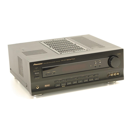
AUDIO/VIDEO MULTICHANNEL AMPLIFIER
VSA-E03
THIS MANUAL IS APPLICABLE TO THE FOLLOWING MODEL(S) AND TYPE(S).
Model
Type
VSA-E03
HYXJI
HYXJI/GR
HVXJI
∗
: Alter the wiring of the Power-supply block at the primary winding of Power-transformer referring to the "Line Voltage Selection" described
in Service Manual.
CONTENTS
1. SAFETY INFORMATION .................................... 2
2. EXPLODED VIEWS AND PARTS LIST ............. 3
......................................................... 6
4. PCB CONNECTION DIAGRAM ....................... 28
5. PCB PARTS LIST ............................................. 41
6. ADJUSTMENT .................................................. 46
PIONEER CORPORATION
PIONEER ELECTRONICS SERVICE, INC. P.O. Box 1760, Long Beach, CA 90801-1760, U.S.A.
PIONEER ELECTRONIC (EUROPE) N.V. Haven 1087, Keetberglaan 1, 9120 Melsele, Belgium
PIONEER ELECTRONICS ASIACENTRE PTE. LTD. 253 Alexandra Road, #04-01, Singapore 159936
c
PIONEER CORPORATION 1999
AUDIO/VIDEO MUL TI-CHANNEL AMPLIFIER
ST ANDBY
ST ANDBY/ON
-
-
OFF
ON
PHONES
Power Requirement
AC220-230V
AC220-230V
AC230V
4-1, Meguro 1-Chome, Meguro-ku, Tokyo 153-8654, Japan
N∫z¿x?≤
DSP
MODE
CHANNEL
CHANNEL
-
+
SIGNAL
LEVEL
SELECT
SELECT
MIDNIGHT
SPEAKERS
B ASS
TREBLE
-
+
-
+
A
B
LOUDNESS
DIRECT
VCR
D VD/LD
TV/SA T
VIDEO
CD
TUNER
MD/T APE
A UX
D VD 5.1CH
The voltage can be converted by the
following method.
AC240V,
AC240V,
AC240V,
7. GENERAL INFORMATION .............................. 47
7.1 DISASSEMBLY .......................................... 47
7.2 PARTS ....................................................... 49
7.2.1 IC ....................................................... 49
7.3 REMOTE CONTROL UNIT ........................ 52
[CU-VSA035 (AXD7237)]
....................................................... 56
MASTER
V OLUME
DO WN
UP
VIDEO INPUT
S-VIDEO
VIDEO
L
A UDIO R
ORDER NO.
RRV2150
∗
∗
∗
T - ZZE JULY 1999 Printed in Japan
Advertisement
Table of Contents

Related Manuals for Pioneer VSA-E03


Summary of Contents for Pioneer VSA-E03
-
Page 1: Table Of Contents
PIONEER CORPORATION 4-1, Meguro 1-Chome, Meguro-ku, Tokyo 153-8654, Japan PIONEER ELECTRONICS SERVICE, INC. P.O. Box 1760, Long Beach, CA 90801-1760, U.S.A. PIONEER ELECTRONIC (EUROPE) N.V. Haven 1087, Keetberglaan 1, 9120 Melsele, Belgium PIONEER ELECTRONICS ASIACENTRE PTE. LTD. 253 Alexandra Road, #04-01, Singapore 159936 PIONEER CORPORATION 1999 T –... -
Page 2: Safety Information
The use of a substitute replacement component which does Leakage 0.5mA current Device not have the same safety characteristics as the PIONEER tester under recommended replacement one, shown in the parts list in test this Service Manual, may create shock, fire, or other hazards. -
Page 3: Exploded Views And Parts List
Operating Instructions See Contrast table (2) Operating Instructions See Contrast table (2) 11(2/2) (2) CONTRAST TABLE VSA-E03/HYXJI, HYXJI/GR and HVXJI are constructed the same except for the following : Part No. Mark No. Symbol and Description Remarks HYXJI Type HYXJI/GR Type... - Page 4 VSA-E03 2.2 EXTERIOR Except HVXJI Type (HVXJI Type Only) ∗ ∗ Note Torque is 12 kg • cm –0 ∗ 19 54 Accessories of Front Panel 59 53 (No. 47) HVXJI Type Only...
- Page 5 Front Panel E03 Assy AMB7648 Binder RNE1277 Cord Clamper RNH-184 (2) CONTRAST TABLE VSA-E03/HYXJI, HYXJI/GR and HVXJI are constructed the same except for the following : Part No. Mark No. Symbol and Description Remarks HYXJI Type HYXJI/GR Type HVXJI Type...
-
Page 6: Block Diagram And Schematic Diagram
VSA-E03 3. BLOCK DIAGRAM AND SCHEMATIC DIAGRAM 3.1 BLOCK DIAGRAM DIGITAL INPUT IC9321 IC9151 MB86342B TC74ACT151AF OPT OUT ANALOG INPUT CODEC IC GAIN CHANGE IC9201 IC9401 & FUNC. SELECTOR NJM2100M CS4226-KQ MIXING IC101 IC9601 TC9274N TC9164AF BUFFER IC109 UPC4570G2 FUNC. SELECTOR... - Page 7 VSA-E03 Note : When ordering service parts, be sure to refer to "EXPLODED VIEWS and PARTS LIST" or "PCB PARTS LIST". RY401 RY628 ELECTRIC 14dB PRE 20dB ATT POWER DSP/6ch IN SELECTOR VOLUME UPC4570G2 AMPLIFIER IC102, IC103 LC7536M LC4966 RY626...
- Page 8 VSA-E03 3.2 OVERALL WIRING CONNECTION DIAGRAM 1/3- FRONT VIDEO DOLBY DIGITAL ASSY ASSY CN9371 (AWX7241) (AWX7196) 1/2, INPUT ASSY (AWX7438) SVIDEO ASSY VIDEO ASSY (AWX7450) (AWX7441)
- Page 9 VSA-E03 POWER SW HEADPHONE MECH SW ASSY ASSY ASSY (AWX7222) (AWX7230) FRONT ASSY (AWX7247) (AWX7439) TRANS 1 ASSY (AWX7287) POWER TRANSFORMER (T1) (ATS7242) TRANS 2 ASSY (AWX7292) BARRIER ASSY (AWX7284) FET ASSY 1/2, (AWX7228) AMP ASSY (AWX7446) J52 J51 FU1 REK-104 (T2.5A) R.C.SP.
- Page 10 VSA-E03 3.3 INPUT ASSY (1/2) CN602 INPUT ASSY(1/2) (AWX7438) • FUNCTION BLOCK 0.01 CN202...
- Page 11 VSA-E03 L ch : AUDIO SIGNAL ROUTE C ch : AUDIO SIGNAL ROUTE (CENTER) FL ch : AUDIO SIGNAL ROUTE (FRONT) CN9801 CN554 ACH7112 3300/35 ACH7113 2200/35 CN507 CN9802 : The power supply is shown with the marked box.
- Page 12 VSA-E03 3.4 INPUT ASSY (2/2) INPUT ASSY(2/2) (AWX7438) • E. VOL BLOCK : The power supply is IC301 LC7535M shown with the marked (LC7536M) box. 120p IC303 LC7535M (LC7536M)
- Page 13 VSA-E03 FL ch : AUDIO SIGNAL ROUTE (FRONT) 120p IC302 LC7535M (LC7536M) 120p...
- Page 14 VSA-E03 3.5 FRONT and POWER SW ASSYS CN111 FRONT ASSY (AWX7439) MASTER VOLUME PDG254A POWER SW ASSY (AWX7222) CN9371...
- Page 15 VSA-E03 CN401 FRONT ASSY S201 : MIDNIGHT S202 : DSP MODE S205 : – BASS S206 : + S207 : – TREBLE S208 : + S209 : A SPEAKERS S210 : B S211 : LOUDNESS S212 : DIRECT S213 :...
- Page 16 VSA-E03 3.6 AMP (1/2), F.SP.CONNECT, R.C.SP.CONNECT, FRONT LARGE and REAR SP ASSYS 4.7/50 C439 220p /500 4.7/50 C1439 10000p R1456 C1442 4.7/50 220p /500 C1441 220p /500 39p 39p 4.7/50 C442 220p /500 4.7/50 C1438 330p AMP ASSY(1/2) (AWX7446) JA413...
- Page 17 VSA-E03 FL ch : AUDIO SIGNAL ROUTE (FRONT) F.SP. CONNECT ASSY 0.22 RETURN (AWX7285) 0.22 FRONT LARGE ASSY (AWX7245) 0.22 0.22 0.22 0.22 AKE7026 C443 220p/500 C444 220p/500 RETURN JA653 AKB7111 0.22 0.22 AKE7042 REAR SP ASSY (AWX7251) 0.22 0.22 R.C.SP.
- Page 18 VSA-E03 3.7 AMP (2/2), HEADPHONE, TRANS 2, TRANS 1, BARRIER, FET and MECH SW ASSYS CN203 AMP ASSY(2/2) (AWX7226) +42.4 –42.4 CN376 : AUDIO SIGNAL ROUTE (HEAD PHONE) ATT7037 HEADPHONE ASSY (AWX7230) VNF-091...
- Page 19 VSA-E03 CAUTION : FOR CONTINUED PROTECTION AGAINST RISK OF FIRE, FET ASSY (AWX7228) REPLACE ONLY WITH SAME TYPE NO. ICP-N70, MFD BY ROHM CO., LTD. FOR IC353. CAUTION : FOR CONTINUED PROTECTION AGAINST RISK OF FIRE, REPLACE ONLY WITH SAME TYPE NO. 491005, MFD BY LITTELFUSE INK.
- Page 20 VSA-E03 3.8 VIDEO, SVIDEO and FRONT VIDEO ASSYS VIDEO ASSY (AWX7441) UPC4570C UPC4570C CN110 UPC4570C UPC4570C...
-
Page 21: Svideo Assy
VSA-E03 : S-VIDEO Y-SIGNAL ROUTE SVIDEO ASSY : S-VIDEO C-SIGNAL ROUTE (AWX7450) : S-VIDEO C-DC ROUTE CN602 CN601 FRONT VIDEO ASSY (AWX7241) PCB BINDER Y20 ADX7248... - Page 22 VSA-E03 3.9 DOLBY DIGITAL ASSY (1/3) : AUDIO SIGNAL ROUTE TC74ACT151AF...
- Page 23 VSA-E03 DOLBY DIGITAL ASSY(1/3) (AWX7196) • INPUT & CODEC BLOCK : The power supply is shown with the marked box. CN113...
- Page 24 VSA-E03 3.10 DOLBY DIGITAL ASSY (2/3)
- Page 25 VSA-E03 DOLBY DIGITAL ASSY(2/3) (AWX7196) • DSP & CONTROL BLOCK CN201...
- Page 26 VSA-E03 3.11 DOLBY DIGITAL ASSY (3/3)
- Page 27 VSA-E03 DOLBY DIGITAL ASSY(3/3) (AWX7196) • FILTER & MUTE BLOCK : AUDIO SIGNAL ROUTE...
-
Page 28: Pcb Connection Diagram
VSA-E03 4. PCB CONNECTION DIAGRAM 4.1 INPUT and FRONT VIDEO ASSYS NOTE FOR PCB DIAGRAMS : 1. Part numbers in PCB diagrams match those in the schematic 3. The parts mounted on this PCB include all necessary parts for diagrams. - Page 29 VSA-E03 CN202 CN554 (ANP7266-B) CN9802 CN9801 CN507 IC102 Q104-Q107 IC101 IC103 Q101-Q103 SIDE A...
- Page 30 VSA-E03 INPUT ASSY IC109 IC307-IC309 IC301- SIDE B...
- Page 31 VSA-E03 (ANP7266-B) 7-IC309 IC301-IC303 IC304-IC306 SIDE B...
- Page 32 VSA-E03 4.2 FRONT and POWER SW ASSYS CN401 POWER Q202 Q205 Q204 Q203 SW ASSY FRONT ASSY SIDE B IC201...
- Page 33 VSA-E03 CN111 (ANP7266-B) FRONT ASSY CN9371 SIDE A Q201 Q207 Q206 (ANP7266-B) POWER ASSY IC201...
- Page 34 VSA-E03 4.3 AMP, HEADPHONE, FET and MECH SW ASSYS (ANP7274-A) (ANP7268-C) MECH SW ASSY FET ASSY HEADPHONE ASSY Q1452 Q1451 SIDE A (ANP7274-A) CN203 AMP ASSY CN112 Q403 Q407 Q404 Q1404 Q1405 IC405 Q401 Q405 Q406 Q402 IC401 Q408 Q1402...
- Page 35 VSA-E03 NEUTRAL AC IN LIVE (ANP7274-A) Q454 IC701 Q701 Q453 Q456 Q458 Q452 IC404 Q711-Q714 IC403 Q1403 Q1401 Q451 Q457 IC402 Q1433 Q1434 Q455...
- Page 36 VSA-E03 4.4 F.SP.CONNECT, R.C.SP.CONNECT, FRONT LARGE and REAR SP ASSYS FRONT LARGE ASSY Q628 Q626 Q627 Q631 Q629 Q630 (ANP7268-C) F.SP. CONNECT ASSY (ANP7274-A) Q652 Q651 (ANP7274-A) R.C.SP. CONNECT ASSY REAR SP REAR SP ASSY ASSY (ANP7266-B) SIDE B SIDE A...
- Page 37 VSA-E03 4.5 TRANS 2, TRANS 1 and BARRIER ASSYS BARRIER ASSY (ANP7274-A) TRANS 2 ASSY CN115 (ANP7274-A) IC351 IC353 POWER TRANSFORMER (T1) Line Voltage Selection Line Voltage can be changed by the following modification: TRANS 1 1. Disconnect the AC power cord.
- Page 38 VSA-E03 4.6 DOLBY DIGITAL ASSY DOLBY DIGITAL ASSY CN201 IC9701 IC9703 Q9605 Q9606 IC9604 CN113 Q9602 Q9604 IC9705 IC9601 IC9602 Q9611 Q9614 IC9704 IC9603 Q9608 Q9610 Q9202 IC9201 Q9615 Q9201 IC9702 Q9616 CN108 IC9391 Q9402 Q9325 Q9324 Q9401 IC9301 IC9323...
- Page 39 VSA-E03 DOLBY DIGITAL ASSY (ANP7296-B) SIDE B...
-
Page 40: Video Assy
VSA-E03 4.7 VIDEO and SVIDEO ASSYS IC501 Q501-Q505 Q506 IC502 IC503 VIDEO ASSY (ANP7274-A) CN110 SVIDEO ASSY Q557 Q556 Q551 Q552 IC553 IC551 IC552 Q554 Q553 CN602 (ANP7268-C) CN109 SIDE A... -
Page 41: Pcb Parts List
VSA-E03 Mark No. Description Part No. Mark No. Description Part No. 5. PCB PARTS LIST • NOTES: Parts marked by "NSP" are generally unavailable because they are not in our Master Spare Parts List. • mark found on some component parts indicates the importance of the safety factor of the part. - Page 42 VSA-E03 Mark No. Description Part No. Mark No. Description Part No. JA101–JA103 PIN JACK(6P) AKB7012 OTHERS CN105 KR CONNECTOR B5B-PH-K-S 4P CABLE HOLDER 51063-0405 CN108 15P PLUG KM200TA15 CN113 7P PLUG KM200TA7 120–122 PCB BINDER VEF1040 AMP ASSY SEMICONDUCTORS FRONT ASSY...
- Page 43 VSA-E03 Mark No. Description Part No. Mark No. Description Part No. C1413, C1414, C421, C422 CEAT4R7M2A COILS AND FILTERS C471, C472 CEAT4R7M2A L627, L628 AF CHOKE COIL ATH1004 C1432, C1433, C1436, C1437 CFTYA224J50 C1417, C1418, C429, C430 CKCYB102K50 SWITCHES AND RELAYS...
- Page 44 VSA-E03 Mark No. Description Part No. Mark No. Description Part No. CAPACITORS TRANS2 ASSY C376, C377 CKCYF103Z50 SEMICONDUCTORS OTHERS IC351, IC352 (5A) AEK7019 IC353 (2.5A) ICP-N70 CN376 3P JUMPER HOLDER 52151-0310 D356 MTZJ20A D357 MTZJ9.1B D354, D355 S5688G VIDEO ASSY...
- Page 45 VSA-E03 Mark No. Description Part No. Mark No. Description Part No. C554, C558, C562, C566 CKPUYY103M16 CAPACITORS C568, C569 CKPUYY103M16 C9159, C9201, C9202, C9324, C9329 CCSRCH101J50 C9331, C9334, C9336, C9338, C9342 CCSRCH101J50 RESISTORS C9420, C9736 CCSRCH102J50 R583, R584 RS2LMF101J C9326, C9327...
-
Page 46: Adjustment
VSA-E03 Mark No. Description Part No. Mark No. Description Part No. 6. ADJUSTMENT OTHERS CN9371 15P CONNECTOR 52044-1545 There is no information to be shown in this chapter. JA9103, JA9104 GP1F32R OPTICAL RECEIVE MODULE JA9107 OPTICAL SEND MODULE GP1F32T CN9801 15P SOCKET... -
Page 47: General Information
VSA-E03 7. GENERAL INFORMATION 7.1 DISASSEMBLY Remove the Bonnet. (seven screws) Release three binders ( ) from the Power Transformer (T1). Remove all screws which fixing the Chassis. Power Transformer (T1) Heat Sink • INPUT Assy (eight screws , Card Spacer ×4... - Page 48 VSA-E03 Open the Chassis and Rear Panel It can be disgnosed under this condition. Show the principal PCB Assemblies in the illustration. INPUT Assy (Side B) AMP Assy (Side B) Chassis Rear Panel Rear View Chassis DOLBY DIGITAL Assy Front Panel...
-
Page 49: Parts
VSA-E03 7.2 PARTS 7.2.1 IC • The information shown in the list is basic information and may not correspond exactly to that shown in the schematic diagrams. 7 PDG254A (FRONT ASSY : IC201) • System Control Microcomputer • Pin Arrangement (Top View) - Page 50 VSA-E03 • Pin Function Pin Name Pin Function Active Grid output 2 Grid output 1 − Connect to VDD ACIN AC pulse input DSPDTIN Data input from CS4226-KQ AC3REQ Data request from MUCAP Digital mode : DIR lock/unlock (L : Lock)
- Page 51 VSA-E03 Pin Name Pin Function Active SVIDEO1 SVIDEO2 TC4051 control (S terminal control) SVIDEO3 TMUTE Tuner mute VMUTE Video mute CDREST CS4226-KQ reset LC4966 Input switch the DVD 6ch (L: DVD 5.1ch) ST_9174 Strobe signal for communication with TC9174 AC3_9164...
-
Page 52: Remote Control Unit
VSA-E03 7.3 REMOTE CONTROL UNIT [CU-VSA035 (AXD7237)] 7.3.1 Exploded Views and Parts List • NOTES: Parts marked by "NSP" are generally unavailable because they are not in our Master Spare Parts List. • mark found on some component parts indicates the importance of the safety factor of the part. - Page 53 VSX-808RDS 7.3.2 Schematic Diagram Note : When ordering service parts, be sure to refer to "EXPLODED VIEWS and PARTS LIST" or "PCB PARTS LIST".
- Page 54 VSX-808RDS 7.3.3 PCB Diagram SIDE A SIDE B...
- Page 55 VSA-E03 7.3.4 PCB Parts List NOTES: ¶Parts marked by "NSP" are generally unavailable because they are not in our Master Spare Parts List. ¶The mark found on some component parts indicates the importance of the safety factor of the part.
-
Page 56: Panel Facilities And Specifications
VSA-E03 8. PANEL FACILITIES AND SPECIFICATIONS 8.1 PANEL FACILITIES Front Section 9 0 - = ~ ! N∫z¿x?≤ AUDIO/VIDEO MUL TI-CHANNEL AMPLIFIER MASTER V OLUME ST ANDBY MODE ST ANDBY/ON CHANNEL CHANNEL SIGNAL – LEVEL SELECT MIDNIGHT SELECT – DO WN... - Page 57 VSA-E03 ~ DSP MODE button Press repeatedly to select a DSP sound mode (HALL 1, HALL 2, JAZZ, DANCE, THEATER 1, or THEATER 2). Use these modes to produce surround sound from standard (two channel) stereo sources. ! MIDNIGHT button Press to hear effective surround sound at low volume levels.
- Page 58 VSA-E03 7 Front View 7 Rear View...
- Page 59 VSA-E03 Display DIRECT SIGNAL MIDNIGHT LOUDNESS SELECT ANALOG PRO LOGIC DIGITAL DIGITAL AC-3 1 SIGNAL SELECT indicators - Program format indicators Light to indicate the type of input signal selected for The following indicators light to show the channels the current component.
- Page 60 VSA-E03 Remote Control Unit 6 MULTI CONTROL buttons These pages describe the buttons on the remote control used to operate the amplifier. Use these buttons to select the remote operation mode. For example, pressing TUNER sets the remote to operate the tuner functions.
-
Page 61: Specifications
VSA-E03 8.2 SPECIFICATIONS Continuous Power Output Accessories (DIN, 1 kHz, T.H.D. 1%, 8 Ω) STEREO Front ........100 W + 100 W SURROUND Front ........... 60 W + 60 W Center ............. 60 W Rear ............60 W Input (Sensitivity/Impedance)
Need help?
Do you have a question about the VSA-E03 and is the answer not in the manual?
Questions and answers