Sign In
Upload
Download
Table of Contents
Contents
Add to my manuals
Delete from my manuals
Share
URL of this page:
HTML Link:
Bookmark this page
Add
Manual will be automatically added to "My Manuals"
Print this page
×
Bookmark added
×
Added to my manuals
Manuals
Brands
datamax-o'neli Manuals
Label Maker
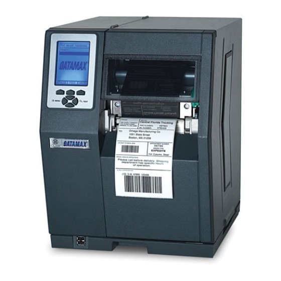
H-4212
Operator's manual
datamax-o'neli H-4212 Operator's Manual
Datamax-o'neil h-class printer operator's manual
Hide thumbs
1
2
3
4
5
6
Table Of Contents
7
8
9
10
11
12
13
14
15
16
17
18
19
20
21
22
23
24
25
26
27
28
29
30
31
32
33
34
35
36
37
38
39
40
41
42
43
44
45
46
47
48
49
50
51
52
53
54
55
56
57
58
59
60
61
62
63
64
65
66
67
68
69
70
71
72
73
74
75
76
77
78
79
80
81
82
83
84
85
86
87
88
89
90
91
92
93
94
95
96
97
98
99
100
101
102
103
104
105
106
107
108
109
110
111
112
113
114
115
116
117
118
119
120
121
122
123
124
125
126
127
128
129
130
131
132
133
134
135
136
137
138
139
140
141
142
143
144
145
146
147
148
149
150
151
152
153
154
155
156
157
158
159
160
161
162
163
164
165
166
167
168
169
170
171
172
173
174
175
176
177
178
179
180
page
of
180
Go
/
180
Contents
Table of Contents
Troubleshooting
Bookmarks
Table of Contents
Limitation of Liability
Important Safety Instructions
Table of Contents
Overview
About the Printer
Standard Features
Optional Features
Getting Started
Unpacking
Additional Requirements
Installation
Connecting the Power Cord
Connecting an Interface Cable
Usb Connection
Connecting to the SDIO Slot and USB Host Ports
Setting up the Printer
Media Loading
Internal Media Sources
External Media Sources
Rewinding Media
Media Sensor Adjustment
Ribbon Loading
Quick Calibration
Print Quality Controls
Using the Control Panel
Layout
The Display
Keypad Functions
The System Menu
Media Settings
Print Control
Printer Options
System Settings
Communications
Diagnostics
MCL Options
The Test Menu
Print Quality Label
Ribbon Test Label
Test Label
Validation Label
Print Configuration
Print Last Label
User-Defined Label
Operating, Adjusting and Maintaining the Printer
Displayed Messages
Prompts and Condition Messages
Calibration
Standard Calibration
Advanced Entry Calibration
Reset Methods
Soft Reset
Level One Reset
Level Two Reset
Printhead Assembly Adjustments
Leveling Cam Adjustment
Printhead Pressure Adjustment
Maintenance
Cleaning the Printhead
Cleaning the Fan Filter
Cleaning the Interior Compartment
Cleaning the Media Sensing Components
Cleaning the Platen and Assist Rollers
Cleaning the Ribbon Path Components
Cleaning the Exterior Surfaces
Updating the Firmware
Updating the Boot Loader
Downloading Fonts
Replacing the Printhead
Troubleshooting
Problem Resolution
General Resolutions
Warning and Fault Messages
Fault Messages
Hex Dump Mode
Specifications
General
Model-Specific Specifications
Approved Media and Ribbon
Appendix A
Module Assignments, and File Handling Definitions and Messages
Appendix B
Resolutions, Widths, Speeds, Emulations, & Custom Adjustments
Appendix C
RS-422/485 Port Configuration
Appendix D
Changing the Menu Language
Appendix E
Saving a Configuration File
Appendix F
Ethernet Setup
Appendix G
Printer Driver and Port Setup
Glossary
Advertisement
Quick Links
Download this manual
Operator's Manual
Table of
Contents
Previous
Page
Next
Page
1
2
3
4
5
Advertisement
Table of Contents
Need help?
Do you have a question about the H-4212 and is the answer not in the manual?
Ask a question
Questions and answers
Related Manuals for datamax-o'neli H-4212
Label Maker datamax-o'neli H-6210 Operator's Manual
Datamax-o'neil h-class printer operator's manual (180 pages)
Label Maker datamax-o'neli H-6308 Operator's Manual
Datamax-o'neil h-class printer operator's manual (180 pages)
Label Maker datamax-o'neli H-8308X Operator's Manual
Datamax-o'neil h-class printer operator's manual (180 pages)
This manual is also suitable for:
H-4310
H-4212x
H-4310x
H-4408
H-4606
H-4606x
...
Show all
H-6210
H-6212x
H-6308
H-6310x
H-8308x
Table of Contents
Save PDF
Print
Rename the bookmark
Delete bookmark?
Delete from my manuals?
Login
Sign In
OR
Sign in with Facebook
Sign in with Google
Upload manual
Upload from disk
Upload from URL


Need help?
Do you have a question about the H-4212 and is the answer not in the manual?
Questions and answers