Advertisement
Table of Contents
- 1 Installation Guide
- 2 About this Guide
- 3 Intended Audience
- 4 Contact Information
- 5 Package Contents
- 6 Installing the C
- 7 Connect C-75 to the Network
- 8 Configuring AP through Config Shell
- 9 Log in and Change the Default Password
- 10 Set Server Discovery
- 11 Configure Network Settings
- 12 C-75 Config Shell Commands
- 13 Appendix A: Access Point (AP)-Server Mutual Authentication
- Download this manual
Advertisement
Table of Contents

Related Manuals for AirTight C-75


Summary of Contents for AirTight C-75
-
Page 1: Installation Guide
Installation Guide C-75 Access Point ©2014 AirTight Networks, Inc. All rights reserved. 339 N. Bernardo Avenue, # 200, Mountain View, CA 94043 www.airtightnetworks.com... - Page 2 This page is intentionally left blank.
- Page 3 Please read the End User License Agreement before installing the C-75 Access Point. The End User License Agreement is available at the following location http://www.airtightnetworks.com/fileadmin/pdf/AirTight-EULA.pdf. Installing the C-75 Access Point constitutes your acceptance of the terms and conditions of the End User License Agreement. DISCLAIMER THE INFORMATION IN THIS GUIDE IS SUBJECT TO CHANGE WITHOUT ANY PRIOR NOTICE.
- Page 4 FOR COUNTRY CODE SELECTION USAGE (WLAN DEVICES) Note: The country code selection is for non-US model only and is not available to all US model. Per FCC regulation, all WiFi product marketed in US must fixed to US operation channels only. C-75 Installation Guide...
- Page 5 Cet équipement est conforme aux limites d'exposition aux rayonnements IC établies pour un environnement non contrôlé. Cet équipement doit être installé et utilisé avec un minimum de 20 cm de distance entre la source de rayonnement et votre corps. C-75 Installation Guide...
-
Page 6: About This Guide
4. Manually Configuring C-75 5. Config Shell Commands 6. Troubleshooting Note: All instances of the term ‘server’ in this document refer to the AirTight Wi-Fi / AirTight WIPS server, unless the server name or type is explicitly stated. Product and Documentation Updates To receive important news on product updates, please visit our website at http://www.airtightnetworks.com. -
Page 7: Package Contents
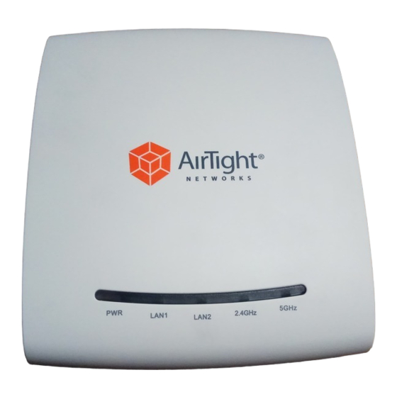
Package Contents Please ensure that the items shown in Figure 1-1 are included in the C-75 device package: Figure 1-1 C-75 Package Contents Note: The MAC address of the device is printed on a label at the bottom of the product and the packaging box. - Page 8 C-75 Overview C-75 is a 3x3 802.11a/b/g/n/ac access point. This chapter provides an overview of the C-75 and describes front and the rear panels. The front panel of the C-75 has 5 LEDs that indicate the working of the device.
- Page 9 Note: LAN2 is ON if the link is up, and is OFF if the link is down. The 2.4 GHz and 5 GHz LEDs blink when there is activity on the respective radio(s). C-75 Installation Guide...
- Page 10 The rear panel of the C-75 has an Ethernet port labeled LAN1, that enables you to connect the device a wired LAN through a switch or a hub and provides the power for the device by using the 802.3af standard.
- Page 11 The Reset Pin Hole and the USB port are on the right side of the device as shown in the figure above. The Reset Pin Hole resets the C-75 device to factory defaults. To reset the device, power cycle the device (remove the power cable once and connect it back again) and while plugging the power cable back into the power source, press and hold down the Reset Pin Hole for 45 seconds until the power, LAN1, 2.4 GHz LEDs go green.
-
Page 12: Installing The C
Mount C-75 Take a configured C-75, that is, ensure that a static IP is assigned to the device or the settings have been changed for DHCP. Note the MAC address and the IP address of the device in a safe place before it is installed in a hard-to-reach location. - Page 13 Wall/ Ceiling Mounting Use the mounting bracket to install the C-75 on the ceiling. To mount the device: 1. Attach the mounting bracket to the wall or ceiling by using the mounting hardware kit. 2. Insert the provided short screws into the bottom cover of the C-75 device.
-
Page 14: Connect C-75 To The Network
Power On C-75 A C-75 device can be powered on by 802.3af Class 0 Power Over Ethernet (PoE) of Nominal input voltage 48V DC. You can connect the device to the network using PoE or a power adapter. Connect C-75 to the Network To connect C-75 to the network, perform the following steps. - Page 15 To power on and connect C-75 to the network using PoE, do the following: 1. Connect one end of the network interface cable to the Ethernet port at the rear of the C-75. 2. Connect the other end of the network interface cable to the Ethernet jack that provides PoE power.
- Page 16 1. Ensure that a DHCP server is available on the network to provide network configuration to the C-75. 2. Connect one end of the network interface cable to the Ethernet port at the rear of the C-75. 3. Connect the other end of the network interface cable to an Ethernet jack on the desired subnet.
- Page 17 5. Log on to the server through SSH and run the get sensor list command. You would see a list of all AirTight devices that are recognized by the server. AirTight Cloud Services users can go to the Devices tab and check whether the device is visible under the Devices tab.
-
Page 18: Configuring Ap Through Config Shell
Device is placed on a subnet that is not DHCP enabled. Configuring AP through Config Shell The Config Shell supports a pre-defined set of commands used to configure the C-75 device. Log in to the device console using the SSH shell. -
Page 19: Configure Network Settings
9. Remove the crossover connection to the computer and connect the Ethernet port to the local switch. Configure IPv6 settings C-75 is IPv6 capable. Use the set ipv6 config command to configure advanced options such as DHCP settings, auto negotiation, and manual configuration. - Page 20 To configure the communication key or passphrase kindly refer to Appendix A: AP-Server Mutual Authentication for further details. C-75 Installation Guide...
-
Page 21: C-75 Config Shell Commands
C-75 Config Shell Commands The following tables detail the C-75 config shell commands. Table 5-1 get Commands get Commands Command Description get ap Displays all the currently visible APs Displays network interface speed and mode get interface get ip config... - Page 22 Sets the AP-server shared secret. You must enter a character string, of length between communication 10 and 127, as the shared secret. The string is internally converted to hexadecimal passphrase format. It can be used instead of the set communication key command. C-75 Installation Guide...
- Page 23 Pings an IPv6 host address or Usage: ping6 <IPv6_address/host_name> hostname> Reboots the AP reboot restart Restarts the AP application reset factory Resets the AP to ‘out of the box’ status Upgrades the AP manually from a given IP address upgrade C-75 Installation Guide...
- Page 24 C-75 Troubleshooting Following are the troubleshooting guidelines for C-75. Symptoms Diagnosis Solution The device did not Ensure that the DHCP server is on and available on the receive a valid IP VLAN/subnet to which the device is connected. If the device...
-
Page 25: Appendix A: Access Point (Ap)-Server Mutual Authentication
Note: Although the server is backward compatible, that is, older version APs can connect to a newer version server, this is not recommended. C-75 Installation Guide...
Need help?
Do you have a question about the C-75 and is the answer not in the manual?
Questions and answers